Transmitter, power amplifier and filtering method

a technology of power amplifiers and transmitters, applied in the direction of transmission, electromagnetic wave modulation, modulation, etc., can solve the problems of difficult interoperability of different radio systems, loss of power amplifiers along the transmitter path, and generally a wide bandwidth of power amplifiers, so as to increase the efficiency of the total transmitter chain and increase the efficiency of the power amplifier. , the effect of reducing the heat generated by the power amplifier

Active Publication Date: 2007-09-20
NOKIA TECHNOLOGLES OY
View PDF6 Cites 22 Cited by
  • Summary
  • Abstract
  • Description
  • Claims
  • Application Information

AI Technical Summary

Benefits of technology

[0013] The embodiments of the invention provide several advantages. The filtering requirements after the power amplifier can be relaxed. In transceivers, receiver-band filtering requirements of the duplex filters can be relaxed. This relaxed requirement for attenuation decreases also the transmitter band losses in the duplex filter which in turn increases the total transmitter chain efficiency. Approximately an increase of 1% in power amplifier efficiency can be reached if the losses at the transmitter chain after the power amplifier decrease 0.1 dB. Thus, already a saving of 0.5 dB in losses may increase the power amplifier efficiency with 5% units. This decreases the heat that the power amplifier generates and, therefore, also the reliability of the power amplifier is increased. Furthermore, the gain of the power amplifier can be increased without adding extra filter at the input of the power amplifier. This means that the required output power from a radio frequency integrated circuit (RFIC) may be reduced.
[0014] The design of the proposed filtering arrangement is simple and it may be configured to be used on different frequency bands with minimal changes. The change of the frequency band used may be performed by software.

Problems solved by technology

In multiradio concepts, where the number of different radio systems is increasing all the time, the interoperability of different radio systems is challenging.
However, power amplifiers have usually a broad bandwidth.
The requirements of such filters are strict causing losses also to the transmitter path.
This decreases the total transmitter efficiency and leads to increased power consumption and increased heat in portable transmitters such as mobile phones.
If no filtering is performed before the power amplifier, the capability of the filters after the power amplifier sets a limit to the maximum gain of the power amplifier and can increase the required output power of the transceiver block before the power amplifier.

Method used


Image

  • Transmitter, power amplifier and filtering method
  • Transmitter, power amplifier and filtering method
  • Transmitter, power amplifier and filtering method

Examples


Embodiment Construction

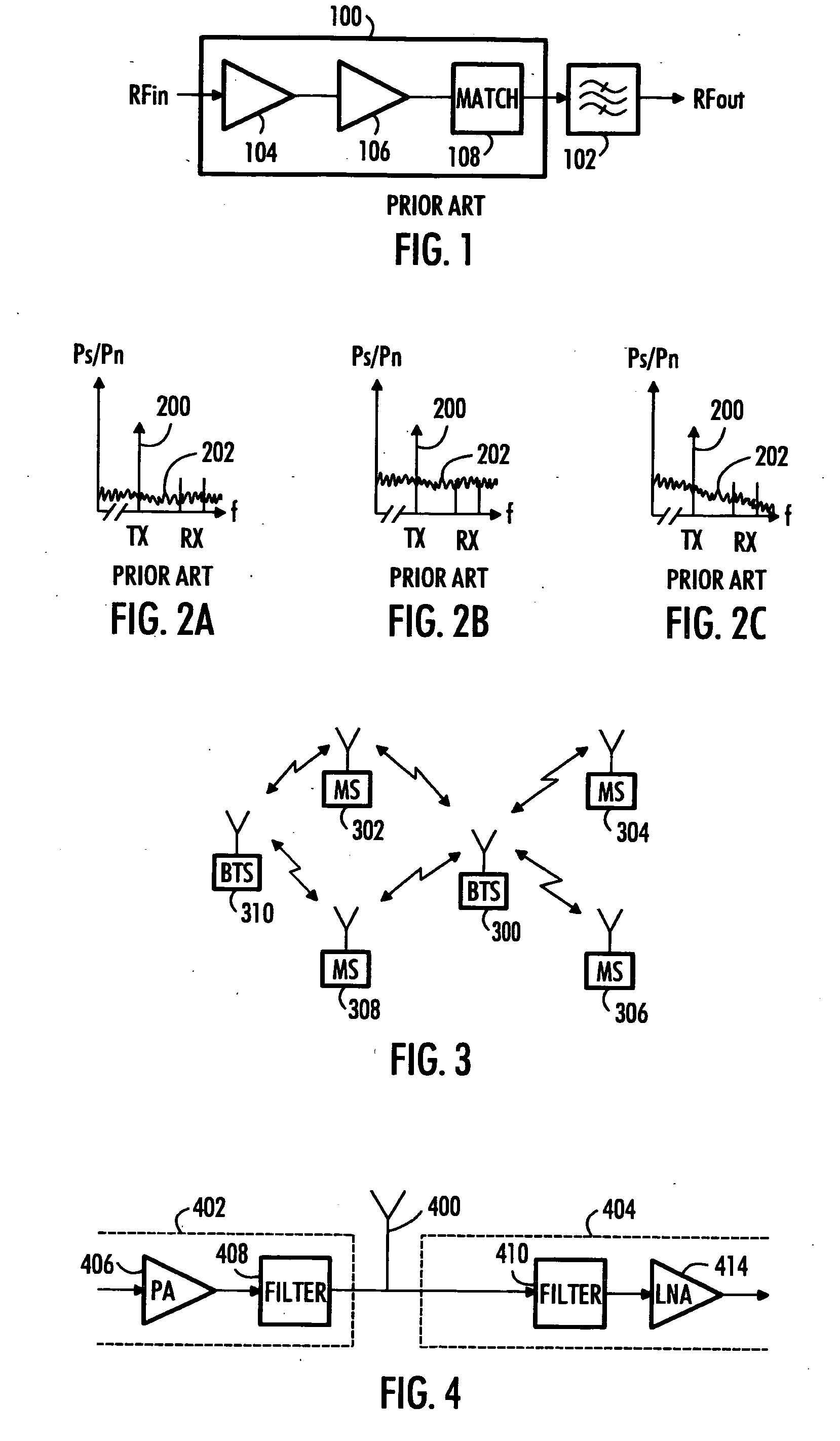
[0026] With reference to FIG. 3, let us examine an example of a telecommunication system in which embodiments of the invention are applicable. FIG. 3 shows a base station 300 which is in connection with terminal equipment 302, 304, 306 and 308. The terminal equipment 302 and 308 may also be in contact with another base station 310. The base station 300 and the terminal equipment 302, 304, 306 and 308 comprise an RF transceiver. Embodiments of the invention may be applied both in base stations and in terminal equipment.

[0027] Different multiple access methods may be used in the telecommunication system in which embodiments of the invention are applicable. The system may utilize CDMA (Code Division Multiple Access) WCDMA (Wide CDMA) or TDMA (Time Division Multiple Access). The access method used is not relevant regarding the embodiments of the invention.

[0028] Embodiments of the invention are not limited to transmitters, transceivers or power amplifiers of transmitters of telecommun...


PUM


Abstract

A filtering method, a transceiver and a transmitter are provided. The transmitter comprises a power amplifier amplifying an RF signal and having multiple stages, and a local oscillator, the power amplifier comprising between at least two stages of the power amplifier an impedance circuitry for forming an impedance at a frequency related to the frequency of the local oscillator, and a switch for switching the impedance of the impedance circuitry means to RF frequency.

Description

FIELD [0001] The invention relates to filtering in transmitters and power amplifiers in transceivers, especially in RF transmitters and RF power amplifiers. BACKGROUND [0002] In multiradio concepts, where the number of different radio systems is increasing all the time, the interoperability of different radio systems is challenging. Different radio systems operating on different frequency bands are required to operate properly without disturbing each other, even if they are operating at the same time. This sets strict requirements for both receiver and transmitter chains especially in transceivers when a transmitter of a transceiver is having high power levels at the same time when a receiver of a transceiver is receiving a weak signal. [0003] In the transmitter, a power amplifier is used to amplify the signal to be transmitted to the required power level. However, power amplifiers have usually a broad bandwidth. Therefore, they amplify the signal to be transmitted not only on the d...

Claims


Application Information

Patent Timeline
Patent Type & Authority Applications(United States)
IPC IPC(8): H04B1/38
CPCH04B1/0475H03H19/008H04B1/04H03G5/00H04B1/40
Inventor ALANEN, MARKO J.VILHONEN, SAMIVILANDER, ARI
Owner NOKIA TECHNOLOGLES OY
Why Eureka
Try Eureka