Control methods for low emission internal combustion system

a control method and internal combustion technology, applied in the direction of electric control, machines/engines, mechanical equipment, etc., can solve the problems of increasing smoke formation, nox aftertreatment technology as presenting cost and durability challenges, and the extent of egr use is generally limited, so as to reduce nox formation and increase the transient response time , good transient response tim

Inactive Publication Date: 2007-09-27
US EPA OFFICE OF GENERAL COUNSEL UNITED STATES OF AMERICA THE
View PDF6 Cites 44 Cited by
  • Summary
  • Abstract
  • Description
  • Claims
  • Application Information

AI Technical Summary

Benefits of technology

[0015] It is also an object of the present invention to provide new methods for controlling NOx formation through management of the charge-air oxygen concentration and for quickly obtaining a desired oxygen concentration of charge-air for combustion, to reduce NOx formation in both steady-state and transient operating conditions.
[0016] In the present invention, low NOx formation and good transient response times in a diesel combustion system are obtained primarily through use of low pressure EGR and methods for quickly obtaining a desired oxygen concentration of charge-air for combustion.
[0017] Under a first method, fuel quantity is controlled in the combustion process to produce exhaust around a target exhaust oxygen concentration value, and to keep the exhaust oxygen concentration levels at a relative constant around that value for medium or high loads. As a result, variance can be reduced in the oxygen concentration of the charge-air mixture that results upon recirculation of a portion of the exhaust. Trimming of the oxygen concentration of charge-air used in combustion (through a high pressure EGR loop or other relatively fast means such as described later herein) may then be performed as desired without increasing transient response time.
[0018] Under an additional or alternative method, a multiple-injection strategy is utilized, in which an early, preliminary fuel injection and combustion event in a cycle produce a desired oxygen concentration of the charge-air to be used for the second, main combustion event for the cycle. In this manner, oxygen concentration control for NOx-reduction during transients may be performed without waiting for transport delays accompanying gross EGR adjustments to control oxygen concentration in the low pressure EGR system.
[0019] By performing transients in a low pressure EGR internal combustion system without waiting for low pressure EGR adjustments to be made, the system's air handling response to meet transients (requiring changes in the overall oxygen amount required for complete combustion in the cylinder) may be paced solely by adjusting the mass of air to be supplied (i.e. boost response), rather than waiting for the determination and / or adjustment of EGR or oxygen concentration levels in the low pressure EGR system in order for the engine demand to be met and / or NOx spikes to be avoided. Transient response paced primarily by boost pressure allows the engine system's response time to be on the same basis as conventional diesel engine response times, even while using a low pressure EGR loop for increased reduction of NOx formation. To the extent that relatively modest excursions of the exhaust oxygen levels or EGR flow rates can be sensed or determined, those skilled in the art have shown equivalent capability to make modest small adjustments in EGR flow through transients in order to maintain the intake oxygen concentration within the required target range.
[0020] In addition, by control of oxygen concentration through transients, engine-out NOx or PM emissions may be reduced, avoiding high NOx or PM spikes. This allows for minimizing the NOx aftertreatment volume or PM aftertreatment volume (or precious metal loading), and thus serves to minimize aftertreatment costs. It also may increase the durability of the NOx aftertreatment or PM aftertreatment devices in that the concentration of NOx or PM taken into the aftertreatment device can be maintained below desired limits. Controlling the NOx concentration of the feedgas to the NOx aftertreatment to avoid excursions beyond upcoming Heavy Duty Not to Exceed (NTE) requirements, at all operating conditions, is further of benefit.

Problems solved by technology

However, industry views such NOx aftertreatment technologies as presenting cost and durability challenges.
Exhaust gas recirculation (EGR) is a known method in the art to lower engine-out NOx emissions, although the extent of EGR use is generally limited by an increase in smoke formation and loss of efficiency that occurs as the EGR ratio reaches high levels.
However, significant use of high pressure EGR requires significant and expensive cooling of the hot recirculated exhaust gas, as well as an adverse pressure differential across the engine to move the EGR from the exhaust to the engine intake system.
As a result, in-cylinder control of NOx formation during transients has been difficult to achieve in the art.
Transient changes in the operating conditions of a diesel engine, such as upon vehicle acceleration, can result in significant NOx or PM emissions if EGR flow rate and level adjustments do not keep up with the changes in fuel feed and boost levels necessary to meet the change in power demand.
Likewise, if intake oxygen concentrations rise in transients, an increase in NOx emissions will result.
Such problems are a common occurrence in the prior art, as it is also conventional to stop exhaust gas recirculation during an increase power demand, which therefore results in an increase in the intake oxygen concentration, and can therefore cause spikes in NOx emissions during such transients.
Such emissions during transient changes can cause vehicles to fail emission standards even where such vehicles could meet the emission standards at steady state conditions.

Method used


Image

  • Control methods for low emission internal combustion system
  • Control methods for low emission internal combustion system
  • Control methods for low emission internal combustion system

Examples


Embodiment Construction

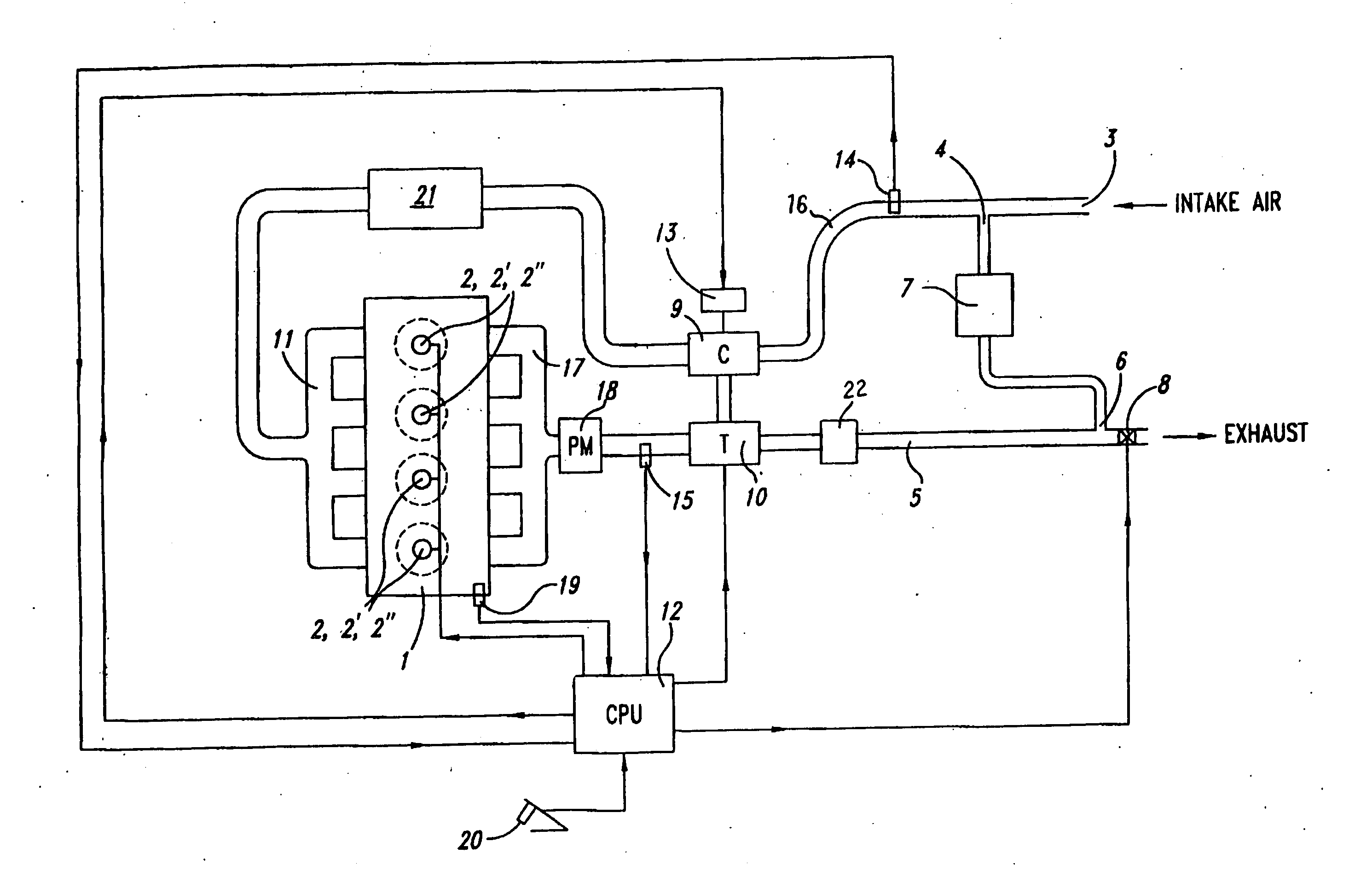
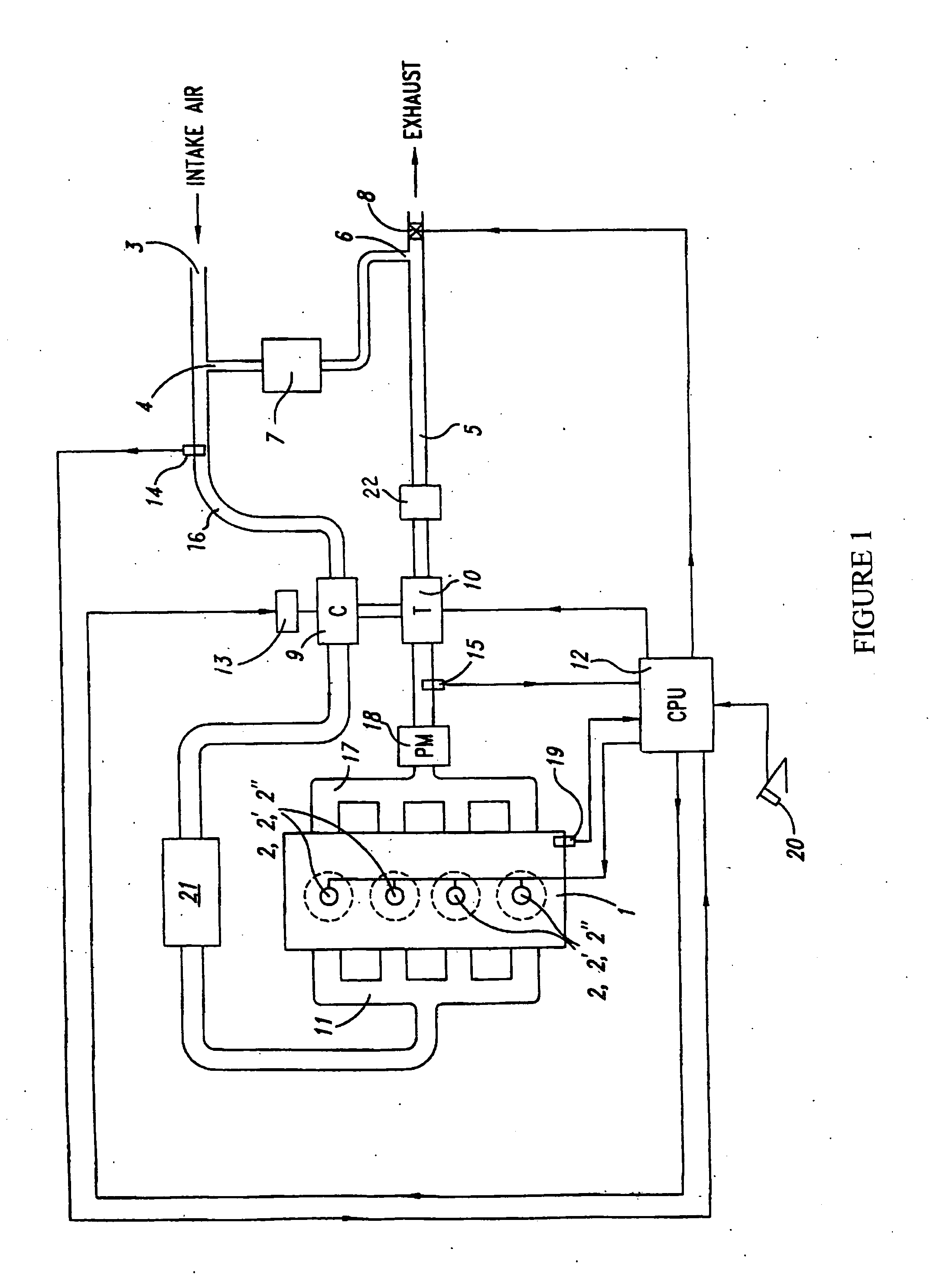
[0023] An internal combustion engine system with low pressure EGR is shown in FIG. 1 in schematic form. It may be noted that FIG. 1 is similar to FIG. 1 of applicant's recently issued U.S. Pat. No. 6,857,263.

[0024] Referring to FIG. 1, an internal combustion diesel engine 1 is shown. Engine 1 receives fuel through direct cylinder fuel injectors 2, 2′, 2″, etc. Engine speed is provided to controller (CPU) 12 by speed sensor 19. Torque command level is provided to controller 12 by accelerator pedal sensor 20. Ambient air enters intake line 16 at port 3. Exhaust gas blends with the ambient air at port 4, thereby forming a charge-air mixture. Exhaust gas is routed from exhaust pipe 5 at port 6 through exhaust gas cooler 7 to port 4. EGR control valve 8 is located just downstream of port 6 in exhaust pipe 5. By restricting flow through valve 8, exhaust gas flow rate through port 6 is controlled. The combined ambient air and recirculated exhaust gas (collectively “charge-air”) flows thro...


PUM


Abstract

Improved transient response times are obtained while maintaining low emissions with a low pressure EGR system through methods for quickly obtaining a desired oxygen concentration for charge-air to be used for combustion. Under a first method, fuel quantity in the main combustion event is controlled in the combustion process to produce exhaust around a relatively constant target exhaust oxygen concentration value. By keeping the exhaust oxygen concentration levels at a relatively constant value, lag time in waiting for low pressure EGR valve adjustments during transients may be avoided, and the system's air handling response to meet transients may be paced solely by adjusting the mass of air to be supplied (i.e. boost response). Under a second method, a multiple-stage combustion process is utilized, in which fuel feed is controlled in a small, preliminary HCCI-type combustion event in order to produce a target oxygen concentration of charge-air to be used for the second, main combustion event. Under a third method, exhaust rebreathing is used to produce a target oxygen concentration of charge-air to be used for combustion.

Description

RELATED APPLICATIONS [0001] This application claims priority from U.S. provisional application 60 / 655,575, filed Mar. 25, 2005.BACKGROUND AND DESCRIPTION OF RELATED ART [0002] 1. Field of the Invention [0003] The present invention relates to EGR and combustion control processes to assist in the cost-effective lowering of harmful NOx emissions produced in diesel internal combustion engines, with good transient response times. [0004] 2. Background of the Invention, and Description of the Related Art [0005] The continuing use of diesel engines in motor vehicles greatly adds to the atmospheric presence of harmful pollutants such as nitrogen oxides (NOx). Conventional diesel engines emit NOx substantially in excess of acceptable environmental levels. Nevertheless, because of their fuel efficiency, diesel engines remain preferable to gasoline engines for many applications. Attempts to reduce NOx emissions from diesel engines have therefore continued for many years. [0006] There is a need ...

Claims


Application Information

Patent Timeline
Patent Type & Authority Applications(United States)
IPC IPC(8): F02M25/06F01N5/04F01N3/00
CPCF01N3/08Y02T10/47F02B3/06F02B29/0406F02D9/04F02D41/0007F02D41/0065F02D41/107F02D41/3035F02D2250/36F02M25/0707F02M25/0709F02M25/0713F02M25/0718F02M25/0727F02M25/0755Y02T10/128Y02T10/144F02B1/12F02M26/05F02M26/06F02M26/10F02M26/15F02M26/23F02M26/46Y02T10/12Y02T10/40
Inventor HAUGEN, DAVID JAMES
Owner US EPA OFFICE OF GENERAL COUNSEL UNITED STATES OF AMERICA THE
Why Eureka
Try Eureka