

Method and plant for integrated monitoring and control of strip flatness and strip profile
a technology of flatness and strip profile, applied in the direction of profile control device, measuring device, manufacturing tool, etc., can solve the problems of partial flatness measurement, difficult direct contact measurement of strip flatness or tension stress profile, and different flatness or tension profile, etc., to inhibit strip buckling
- Summary
- Abstract
- Description
- Claims
- Application Information
AI Technical Summary
Benefits of technology
Problems solved by technology
Method used
Image

Examples
Embodiment Construction
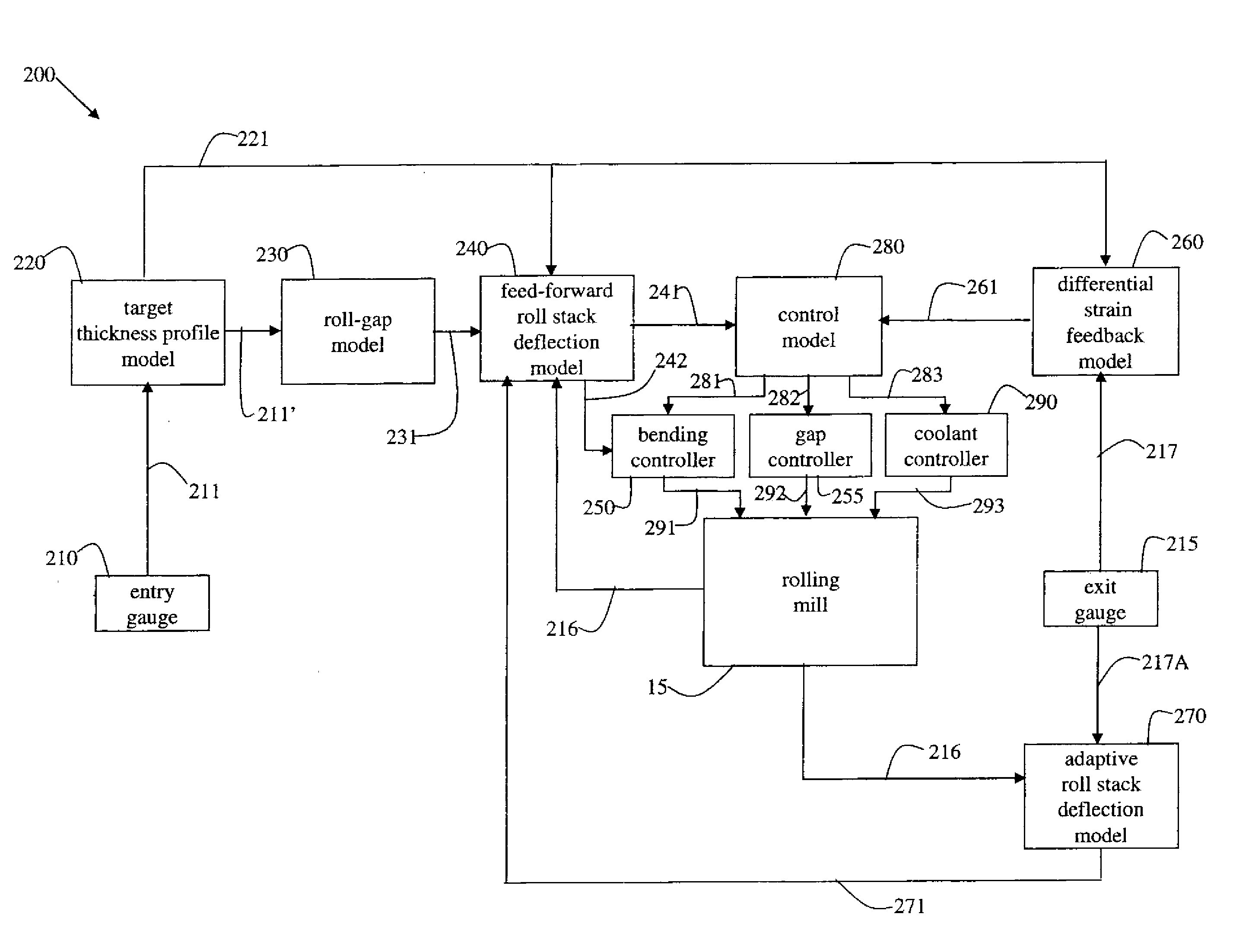
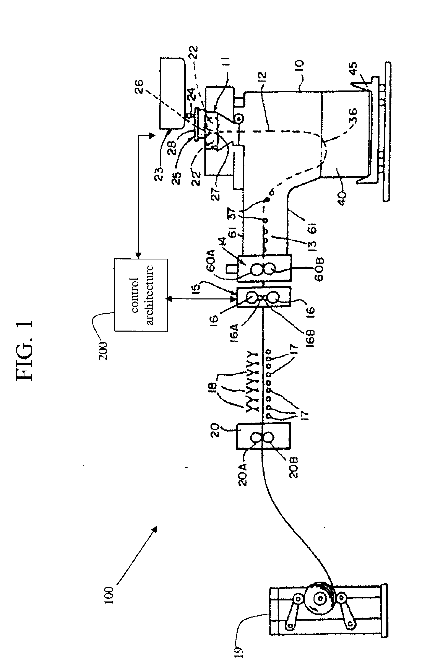
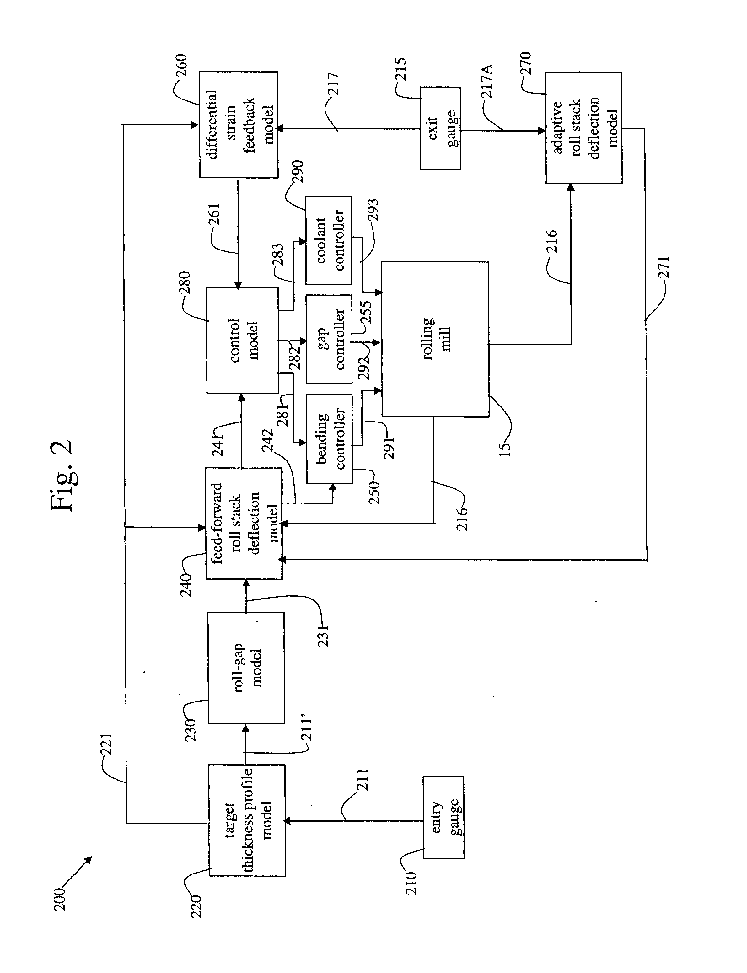
[0057]FIG. 1 is a schematic drawing illustrating a thin strip casting plant 100 having a rolling mill 15 and a control architecture 200. The illustrated casting and rolling installation comprises a twin-roll caster, denoted generally by 11, which produces thin cast steel strip 12 and comprises casting rolls 22 and side dams 26. During operation, the casting rolls are counter-rotated by a drive (not shown). A metal delivery system comprising at least a moveable tundish 23, a large tundish 25, and a core nozzle 24 provides molten steel to the twin roll caster 11. Thin cast steel strip 12 passes downwardly through a nip 27 between the casting rolls 22 and then into a transient path across a guide table 13 to a pinch roll stand 14. After exiting the pinch roll stand 14, thin cast strip 12 passes into and through hot rolling mill 15 comprised of back up rolls 16 and upper and lower work rolls 16A and 16B, where the geometry (e.g., thickness, profile, and / or flatness) of the strip may be ...
PUM
| Property | Measurement | Unit |
|---|---|---|
| thickness | aaaaa | aaaaa |
| thickness | aaaaa | aaaaa |
| thickness | aaaaa | aaaaa |
Abstract
Description
Claims
Application Information