Media data synchronization in a wireless network

Active Publication Date: 2007-09-27
D & M HOLDINGS INC
View PDF16 Cites 133 Cited by
  • Summary
  • Abstract
  • Description
  • Claims
  • Application Information

AI Technical Summary

Benefits of technology

[0016] One embodiment of the invention includes a method at a master device in an infrastructure network having an access point and client devices, each client device having a global clock and a local clock, the respective global clocks being synchronized. Each client device has a global clock and a local clock. The method includes reading a master local clock included in the master device to obtain a master local clock counter value. The method further includes reading a master global clock included in the master device to obtain a master global clock value corresponding to the read master local clock counter value. The method further includes sending data to at least one client device that provides to a receiving client

Problems solved by technology

Failure to accurately synchronize multi-channel audio playback will result in the production of unwanted artifacts.
The inventors and others have found that it is very difficult to achieve a good precision of time error measurement using an NTP-used method in a wireless network.
Such a latency depends on the traffic intensity and behaves significantly worse than a switched wired Ethernet network.
The inventors have found that even quite sophisticated methods of assessing the quality of time error

Method used


Image

  • Media data synchronization in a wireless network
  • Media data synchronization in a wireless network
  • Media data synchronization in a wireless network

Examples


embodiment 300

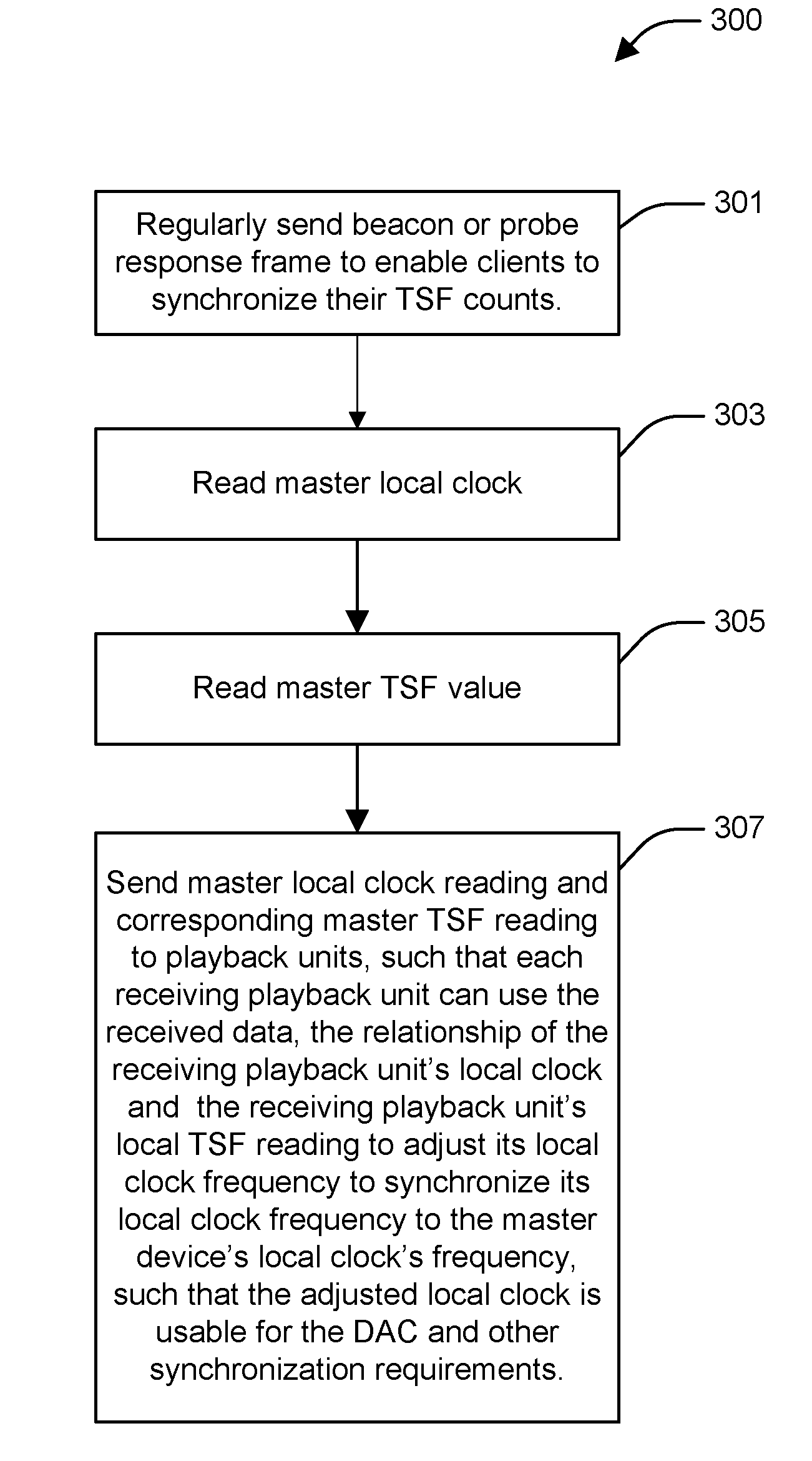
[0065]FIG. 3 shows a flowchart of one method embodiment 300 operating in the master device such as device 200 that in one embodiment is in playback unit 106. In one embodiment, the master device is also the IEEE 802.11 access point.

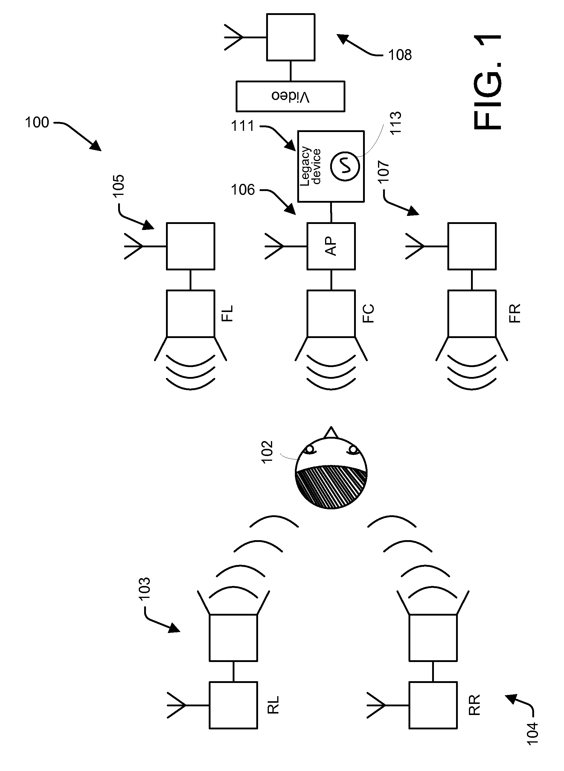
[0066] In 301, the method includes the access point, e.g., master device 106 regularly, although not necessarily in a periodic fashion, sending beacon frames to enable client stations to synchronize their TSF counts. 301 also includes the master device 106 optionally sending one or more probe response frames in response to receiving a corresponding probe request frame.

[0067] In the alternate arrangement of a separate access point, 301 is replaced by the master device 106 being a client device of the access point and receiving one or more beacon frames or probe response frames from the access point to synchronizing its TSF count.

[0068] In 303, the method 300 reads the master's local clock counter value, e.g., from the clock value 222 of the clock control...

embodiment 400

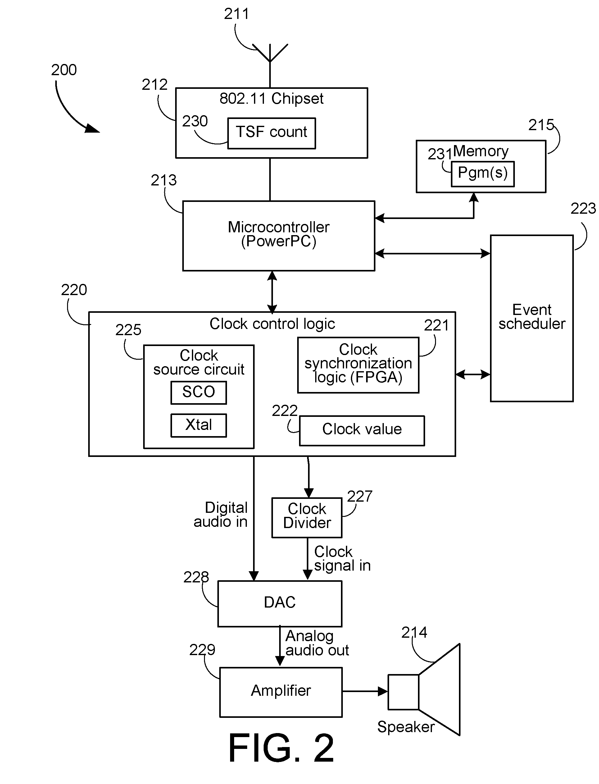
[0072]FIG. 4 shows a simplified flowchart of a method embodiment 400 operating at a client device, e.g., client device 103 acting as a slave device. The method is implemented, e.g., as software in the memory of the client device, e.g., memory 215 in the case the client device 106 follows the architecture 200 of FIG. 2. In one embodiment, some of the method of 400 is implemented by the clock control logic 220 as a combination of software executing in the microcontroller and logic in the clock synchronization logic 221.

[0073] In 401 the slave device receives one or more beacon frames or probe response frames sent by the access point, e.g., master device 106 in the arrangement of FIG. 1, or the access point 901 in the example arrangement of FIG. 9, and synchronizes its local TSF, e.g., local TSF count 230 in the case the client as the architecture shown in FIG. 2.

[0074] In 403 the slave device 103 receives data sent by the master device 106 indicative of a master clock count and the c...


PUM


Abstract

A method of keeping global time in a wireless network, the method comprising the steps of: using a first 802.11 chip set to read a Time Synchronization Function (TSF) to provide an initial time base; using an interconnected clock control circuit to read the TSF time directly from the 802.11 chip set and to implement a local clock based on time values read from the TSF function.

Description

RELATED PATENT APPLICATION [0001] The present application claims benefit of priority of and is a conversion of U.S. Provisional Patent Application 60 / 755,243 filed Dec. 30, 2005 to inventors Celinski et al., titled MEDIA DATA SYNCHRONIZATION IN A NETWORK ENVIRONMENT, Docket / Ref. No. GECK101P. The contents of Provisional Application 60 / 755,243 are incorporated herein by reference.FIELD OF THE INVENTION [0002] The present invention relates to synchronization of media streams for playback and, in particular, discloses a form of accurate synchronization of multiple media output streams in an audio visual wireless playback arrangement. BACKGROUND OF THE INVENTION [0003] Wireless networks are becoming increasingly popular. It is often desirable to provide for accurate playback of multiple audio and visual channels in a networked environment. In particular, wireless speakers systems are also becoming increasingly popular, and often multiple audio playback streams are required. For example,...

Claims


Application Information

Patent Timeline
IPC IPC(8): G06F1/00
CPCG06F1/12H04J3/0664H04W84/18H04S3/00H04S7/00H04R2420/07
Inventor CELINSKI, TOMASZCELINSKI, PETERBRYCE, STUARTRAMSAY, MAX GORDONKENT, ADAM J.KACZYNSKI, ADAM
Owner D & M HOLDINGS INC
Why Eureka
Try Eureka