Integrated liquid to air conduction module

a liquid-to-air conduction module and integrated technology, applied in the field of heat exchangers, can solve the problems of not meeting the requirements of traditional cooling structures, the current cooling structure of semiconductors is significant for traditional cooling structures, and the heat dissipation requirements of performance processors are very high

Active Publication Date: 2007-10-04
VERTIV CORP
View PDF99 Cites 61 Cited by
  • Summary
  • Abstract
  • Description
  • Claims
  • Application Information

AI Technical Summary

Benefits of technology

[0007]Preferably, the fluid path includes a double-counter structure. The double-counter structure is a multi-pass flow structure with the predominant flow path counter to that of the flow in the second medium. The purpose of the multi-pass flow structure is spread the heat over a larger area and to maximize the time during which the fluid is flowing under the air fins and transferring heat. In one embodiment, the system also includes a pump coupled to the fluid path.
[0017]The air fins coupled to the second layer are covered with an enclosure to create one or more air channels. A channel divider, the air fins shape, and the placement of the air fins control the rate and direction of a cooling airflow.
[0018]Preferably, the second layer seals to the first layer to provide an inner surface of the fluid path. In one embodiment, the flow path is optimized to maximize cooling of each electronic device. In another embodiment, the flow path is optimized to minimize the temperature of each electronic device. In yet another embodiment, the flow path is optimized to maximize the cooling of a selected electronic device.

Problems solved by technology

Cooling current semiconductor structures presents significant challenges for traditional cooling structures, such as fan-mounted heat sinks and heat pipes.
For instance, modern high performance processors have very high heat dissipation requirements, but traditional cooling structures cannot satisfy these requirements.
Fan-mounted heat sinks often do not move sufficient air quickly enough to cool a modern processor.
Similarly, heat pipes are limited in both the amount of heat they can dissipate and the distance they can move the heat from the heat source.
Hence, conventional cooling techniques that use heat pipes or fan-mounted heat sinks are not adequate for cooling modern electronics.
These limitations are even more apparent with systems that incorporate multiple electronic components, each generating heat.
Cooling solutions addressing cooling on an individual component basis decreases the system reliability by requiring additional critical components, joints, and connections, failure of any one of which could cause a system failure.

Method used


Image

  • Integrated liquid to air conduction module
  • Integrated liquid to air conduction module
  • Integrated liquid to air conduction module

Examples


first embodiment

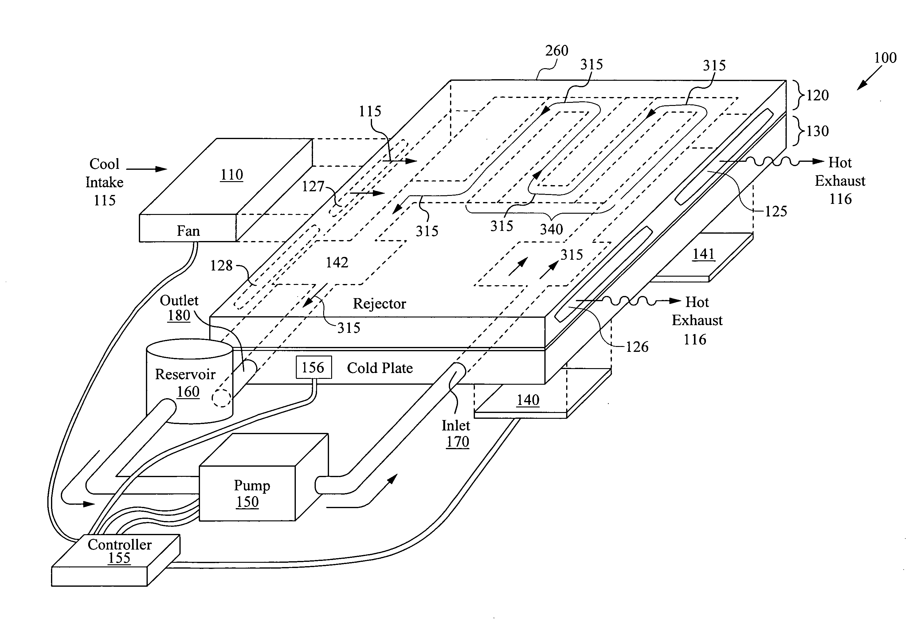
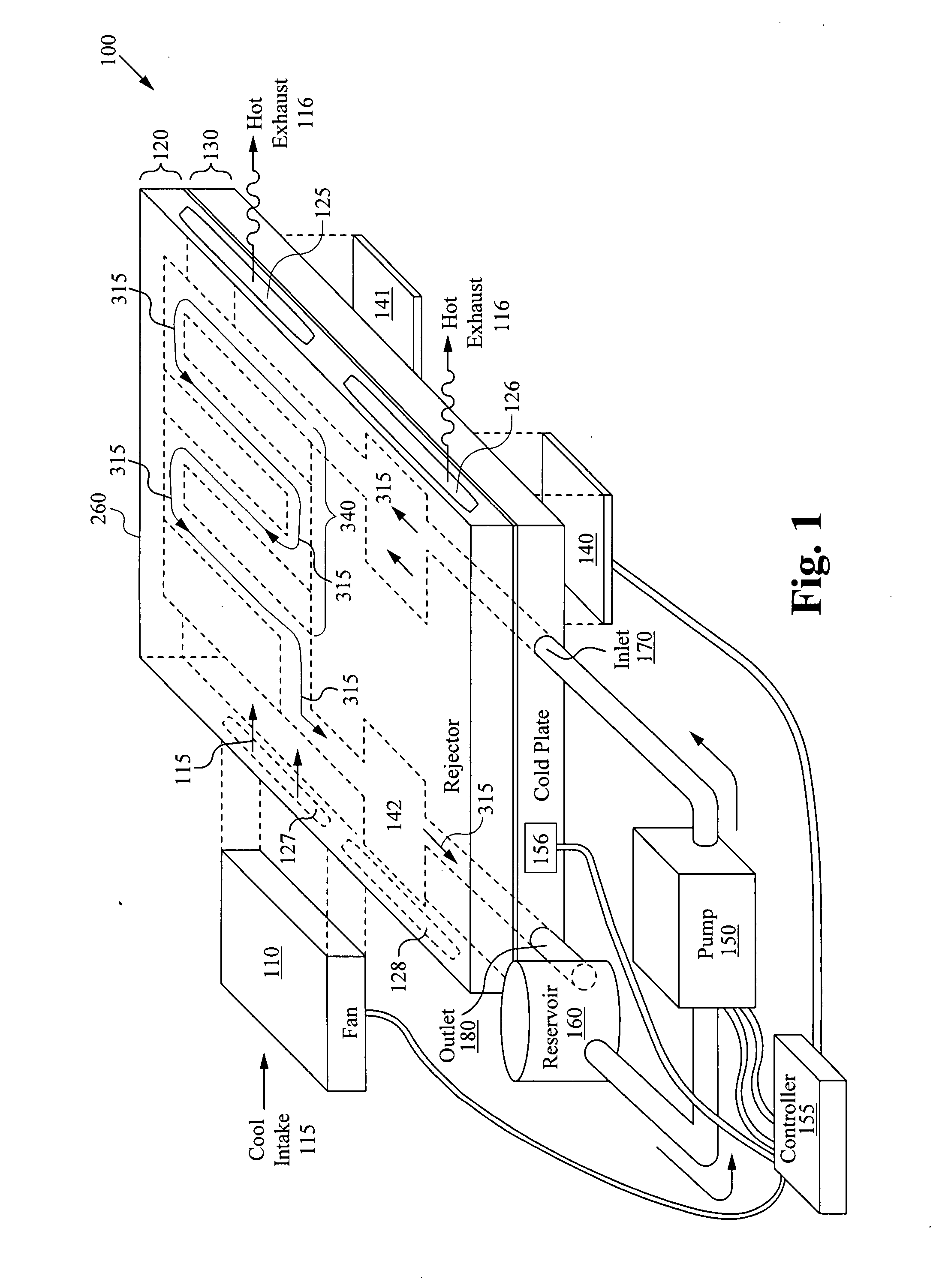
[0037]FIG. 1 is a perspective view of a preferred embodiment of an integrated cooling system 100 for cooling a laptop computer according to the present invention. The cooling system 100 includes a cold-plate assembly 130 coupled to a heat-rejector assembly 120, thereby forming an integrated cold-plate heat-rejector assembly. One surface of the heat-rejector assembly 120 is adjacent to the cold-plate assembly 130 and forms a top plate and seals to the cold-plate assembly 130. The integrated cold-plate heat-rejector assembly overlies and thus cools first, second, and third electronic devices 140-142, respectively.

[0038]The heat-rejector assembly 120 includes air vents 125-127, all fluidly coupled to a cooling fan 110. The cold-plate assembly 130 includes an inlet 170 and outlet 180 fluidly coupled to the flow path 315. Coupled to the inlet 170 and outlet 180 is a pump 150. The pump 150, integrated cold-plate 130 heat-rejector 120 assembly, and reservoir 160 thus form a closed loop flu...

second embodiment

[0051]FIG. 4 is a perspective view of an integrated cooling system 400 in accordance with the present invention. The integrated cooling system 400 includes a cold-plate assembly 410, coupled to the heat-rejector assembly 420, a pump 430, and a fan 440. Air-fins 421 are coupled to the heat-rejector assembly 420.

[0052]The cold-plate assembly 410 contains a fluid path and fluid which is pumped though the assembly 420 to distribute the heat generated by the heat source 460. The heat-rejector 420 is sealed to the cold-plate and defines an inner surface of the of the fluid path. A pump 430 is coupled to the fluid path though an inlet 431 and an outlet 432. The heat is conducted to the heat-rejector assembly 420, to the air fins 421, and into the ambient air flow generated by the fan 440. Preferably an enclosure 450 covers the heat-rejector assembly 420 forming an air channel. Attached to one end of the air channel is a fan 440 that either pulls or pushes air through the air fins 421.

[0053...


PUM


Abstract

An integrated cooling system for cooling systems such as laptops or subsystems such as a graphics card is disclosed. An integrated cooling system includes a first layer having a contact area configured for coupling to a heat source, wherein the first layer has a fluid path passes adjacent to the contact area where the heat source is in thermal contact with first layer. Coupled to the first layer is a second layer to which a number of air fins are attached. The invention includes a pump that is connected to the fluid path forming a closed path for circulating a fluid through the first layer. Within the first layer, the fluid path will contain a plurality of fluid fins which control the flow of a fluid within the fluid path. Within the fluid path, a structure providing a double-counter flow adjacent to one or more electronic devices. Additionally the fluid path can include a microchannel plate structure. The system can include a includes a programmable controller connect the an air-mover, pump and temperature sensing device. A reservoir can be connected to the fluid path.

Description

RELATED APPLICATIONS[0001]This patent application claims priority under 35 U.S.C. 119 (e) of the co-pending U.S. Provisional Patent Application Ser. No. 60 / 788,545 filed Mar. 30, 2006, and entitled “MULTI CHIP COOLING”. The Provisional Patent Application, Ser. 60 / 788,545 filed Mar. 30, 2006, and entitled “MULTI CHIP COOLING” is also hereby incorporated by reference.FIELD OF THE INVENTION[0002]This invention relates generally to heat exchangers. More specifically, the present invention relates to methods of and systems for cooling multi-chip using a combination of liquid and air cooling structures.BACKGROUND OF THE INVENTION[0003]Cooling current semiconductor structures presents significant challenges for traditional cooling structures, such as fan-mounted heat sinks and heat pipes. For instance, modern high performance processors have very high heat dissipation requirements, but traditional cooling structures cannot satisfy these requirements. Fan-mounted heat sinks often do not mov...

Claims


Application Information

Patent Timeline
Patent Type & Authority Applications(United States)
IPC IPC(8): H05K7/20
CPCG06F1/20G06F2200/201H01L23/467H01L23/473H01L2924/0002H05K7/20281H01L2924/00
Inventor HOM, JAMESUPADHYA, GIRISHWERNER, DOUGLAS E.MUNCH, MARKTSAO, PAULCONWAY, BRUCEZHOU, PENGBREWER, RICHARD
Owner VERTIV CORP
Why Eureka
Try Eureka