Table for Receiving a Workpiece and Method for Processing a Workpiece on Such Table

a workpiece and table technology, applied in the field of tables for receiving workpieces and processing workpieces on such tables, can solve the problems of workpiece deformation, insufficient processing precision, and affecting the distance between workpieces and processing devices in a manner, so as to avoid sagging or bending of the substrate, avoid undesired bending of the workpiece plate, and ensure uniform pressure

Inactive Publication Date: 2007-10-04
OERLIKON SOLAR AG (TRUEBBACH)
View PDF15 Cites 14 Cited by
  • Summary
  • Abstract
  • Description
  • Claims
  • Application Information

AI Technical Summary

Benefits of technology

[0005] Because the workpiece, the plate or the glass plate is supported on an air cushion, the present invention has the decisive advantage that, during processing of the plate-like workpiece, the underside thereof does not come into contact with the top of the table, with the result that undesired soiling or scratching of the underside of the plate or damage to said underside, for example by the table surface or particles is avoided. Furthermore, sagging or bending of the substrate can be avoided by supporting the workpiece on an air cushion. By adjusting the pressure conditions, it is moreover possible to regulate the height within certain limits, which is advantageous in some of the treatment steps. Moreover, the air or gas cushion described permits a (quasi-)friction-free transport of the workpiece on the tabletop. Disc-like or plate-like workpieces, for example glass panes, glass substrates, ceramic plates, wafers of semiconductor material, such as silicon, are to be considered here in particular as workpieces. These plates may reach areas of, for example, 2 m2 or more and at the same time have a thickness of, for example, only 1 mm or less, i.e. may have a large area but may be thin, and they consist as a rule of a brittle material, such as glass or ceramic.
[0006] The device of the invention preferably has a table or a tabletop, which is composed of at least two segments. That surface of a segment which faces the workpiece has a plurality of outlet orifices or outlet channels extending equidistant to one another and arranged in rows for the pressurized gas of the pressure-device, which orifices or channels are coupled to the pressure device so as to permit passage of fluid. The outlet orifices of the pressurized gas are distributed uniformly over substantially the entire top of the table, with the result that a uniform pressure is generated on the workpiece supported on the air cushion and hence undesired bending of the workpiece plate is avoided.
[0007] The device of the invention preferably has a suction apparatus for sucking the pressurized gas from the top face of the table which faces the workpiece or of the tabletop. This has the advantage that the prevailing fluid pressure in the supporting gas cushion can be controlled via the pressure difference between the pressure side at high pressure and the suction side at at least lower pressure. Consequently, the pressure in the gas cushion or air cushion can also be set in such a way that the disc-like workpiece maintains the specified processing height for the processing.
[0008] The table (or in the same context a segment) preferably has, on its surface facing the workpiece, a plurality of suction orifices which are uniformly distributed over the top face of the table or of the tabletop and which are coupled to the suction apparatus so as to permit passage of fluid. This permits uniform suction, viewed over the entire top face of the table or top face of the segment, and thus also achieves on the workpiece a resultant pressure distribution distributed and prevailing uniformly over the entire table or segment area. The table of the invention preferably has, in or on its top face-facing the workpiece, a plurality of suction channels, suction grooves or depressions as suction orifices which extend equidistant in succession along the longitudinal direction of the table and which—preferably—extend in each case without interruption substantially over the total width of the table, with the result that the suction of fluid or air uniformly over the area is improved.

Problems solved by technology

In the case of large-area thin workpieces, however, there is always a sag which influences the distance between workpiece and processing device in a manner which is not completely controllable, necessitating at least further precautions in the case of high accuracy requirements, in certain circumstances also not permitting sufficient precision in processing.
Owing to the unavoidable roughness of the support surface, however, local deformations of the workpiece, which are substantially smaller but, for example, in the production of structures in the micron and submicron range, are still troublesome, cannot be completely ruled out in this case too.
Moreover, there is a not insignificant risk that the workpiece will be scratched by direct contact with the support surface or its surface would be damaged in another manner.
This can lead to waste, especially in the processing of substrates for the semiconductor industry, such as large-area wafers.

Method used


Image

  • Table for Receiving a Workpiece and Method for Processing a Workpiece on Such Table
  • Table for Receiving a Workpiece and Method for Processing a Workpiece on Such Table
  • Table for Receiving a Workpiece and Method for Processing a Workpiece on Such Table

Examples


Embodiment Construction

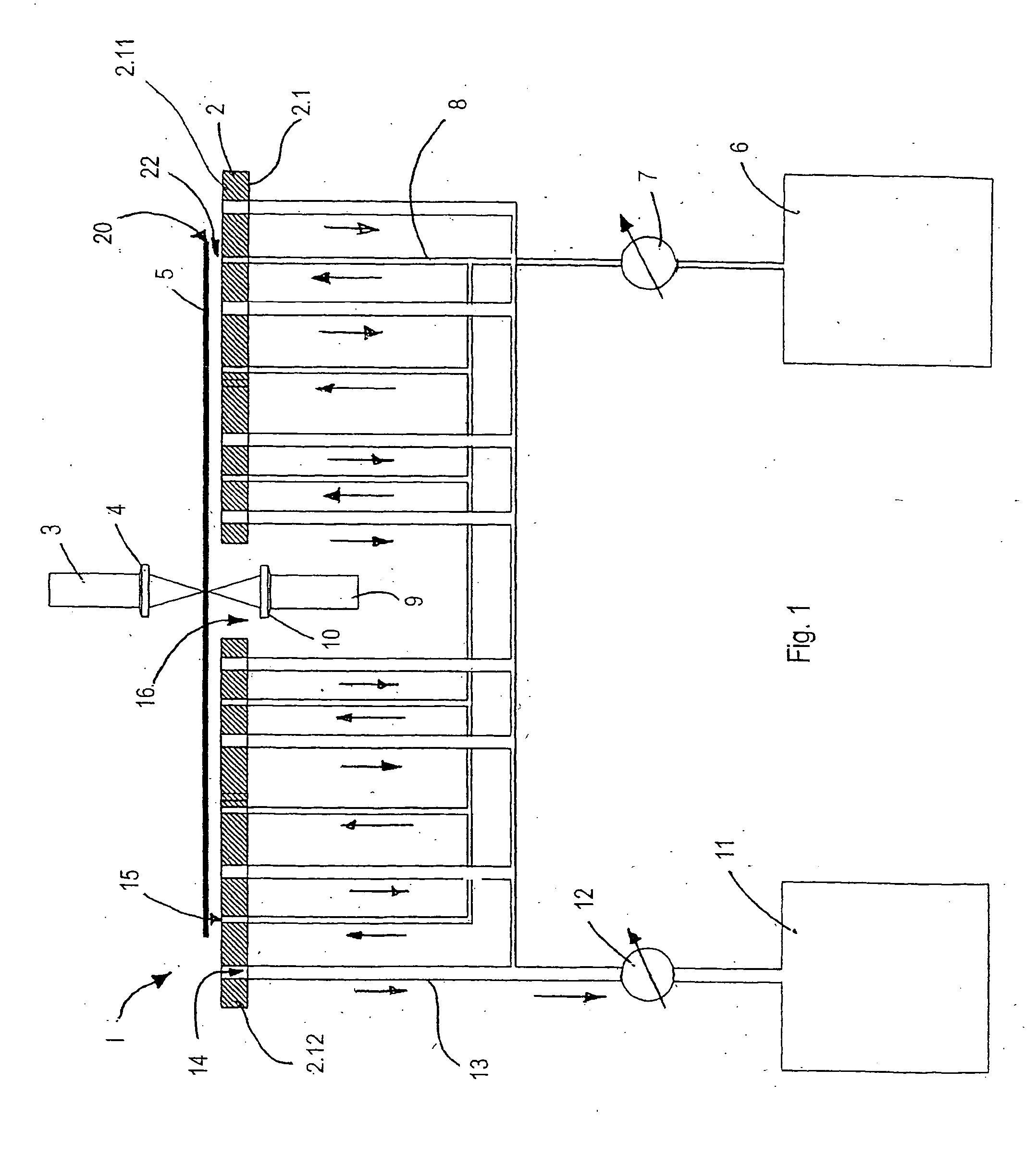
[0017]FIG. 1 shows a device 1 comprising a table 2 according to the invention; shown schematically as a processing device is a laser apparatus, a flow generation apparatus having a take-off apparatus 11 and a pressure generation apparatus 6 which releases a pressurized fluid, e.g. nitrogen or another gas or gas mixture, in this case air. The disc-like workpiece 5 is, for example, a glass plate, a ceramic plate or another plate of brittle substrate material which is to be processed by means of the laser apparatus. In the present exemplary and preferred embodiment of the invention according to FIG. 1, the disc-like workpiece 5 is a substrate ceramic plate or a glass substrate plate.

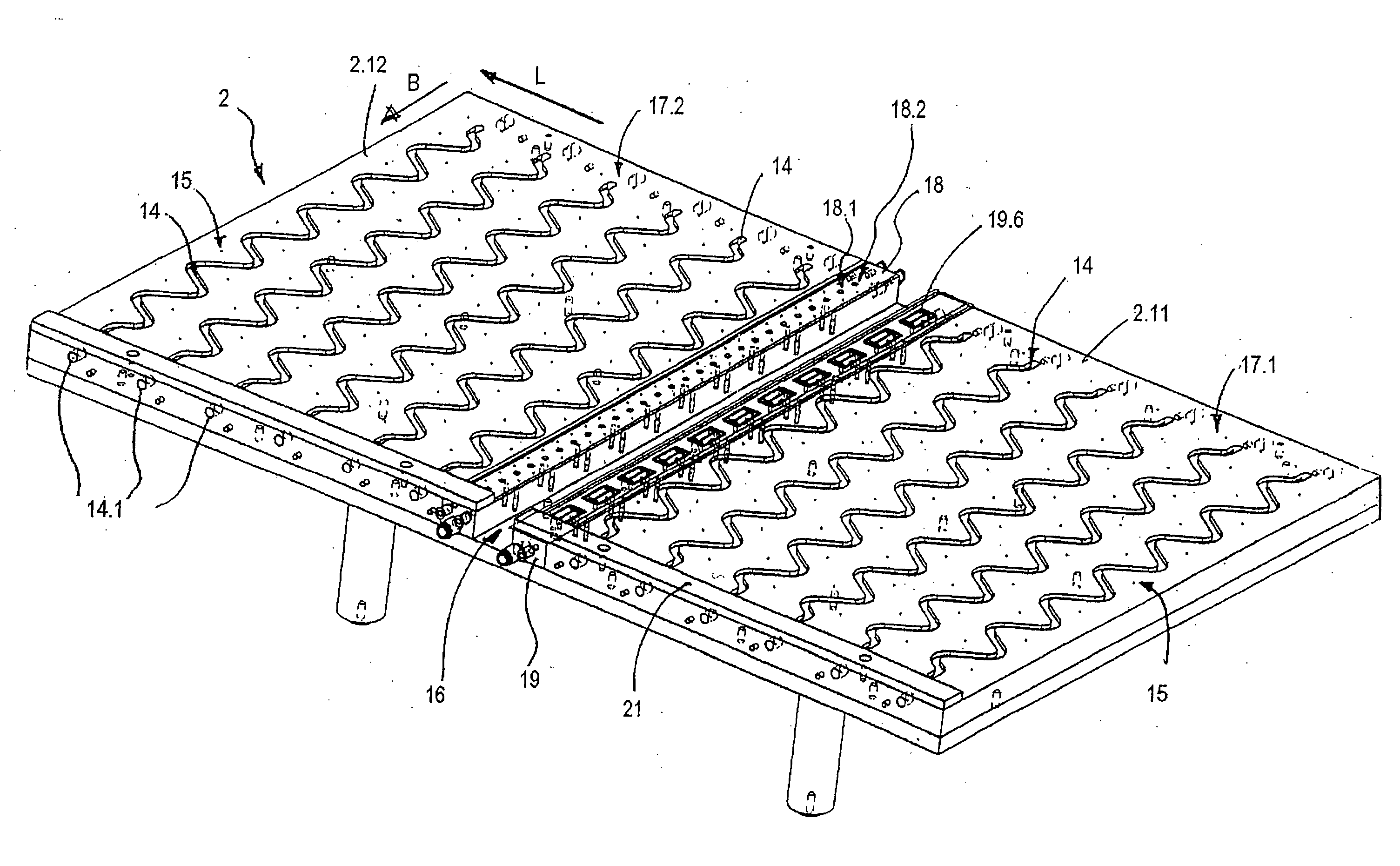
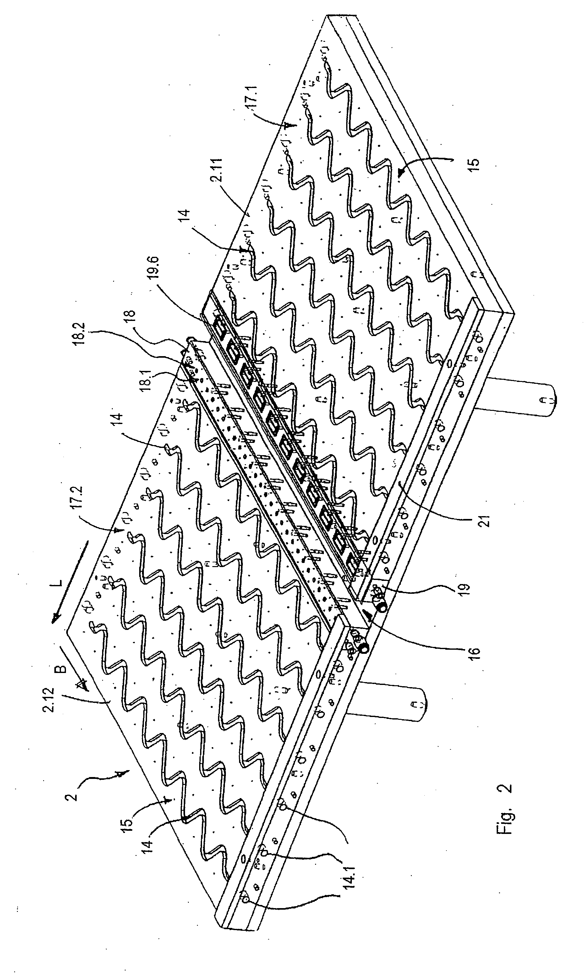
[0018] The table 2 substantially comprises a tabletop 2.1 which forms a support surface facing upwards. It comprises two segments which are in the form of two rectangular halves 2.11 and 2.12 of equal size. The top faces 17.1 and 17.2 of the segments 2.11, 2.12 each form an extensive section of the support...


PUM

PropertyMeasurementUnit
diameteraaaaaaaaaa
diameteraaaaaaaaaa
diameteraaaaaaaaaa

Abstract

The present invention relates to a device for the treatment of a workpiece, in particular of a substantially flat substrate, comprising a table (2) for supporting the workpiece (5), a flow generation apparatus (6, 11) producing a gas flow (22) on a top face (17.1, 17.2) of the table (2) in a region between the workpiece (5) and the top face (17.1, 17.2) of the table (2), on which gas flow the workpiece (5) is supported during the treatment.

Description

FIELD OF THE INVENTION [0001] The invention relates to a table for receiving a workpiece according to the pre-characterizing clause of claim 1 and a method for processing a workpiece on a table according to the invention. Such tables are used, for example, for the processing of plate-like workpieces, such as glass plates, by means of lasers, for example for laser scribing or cutting. PRIOR ART [0002] It is known that glass plates and similar workpieces can be clamped at two opposite edges and processed, usually from the top. In the case of large-area thin workpieces, however, there is always a sag which influences the distance between workpiece and processing device in a manner which is not completely controllable, necessitating at least further precautions in the case of high accuracy requirements, in certain circumstances also not permitting sufficient precision in processing. [0003] In comparison, it is possible to place the workpiece on a continuous flat support surface and thus...

Claims


Application Information

Patent Timeline
Patent Type & Authority Applications(United States)
IPC IPC(8): B23Q1/25B65G49/06C03B33/03C03B33/08
CPCB23K26/10B23K26/14B23K26/408B23K26/422B28D5/0082B65G49/061C03B33/093B65G2249/04B65G2249/045C03B33/03C03B33/037C03B33/082B65G49/065B23K26/702B23K26/40B23K2103/52Y10T83/2194Y10T225/325Y10T83/0341Y10T83/533Y10T83/2185Y10T225/12Y10T83/476Y10T225/371H01L21/02
Inventor GRUNDMULLER, RICHARDMEIER, JOHNNESBUCHEL, ARTHUR
Owner OERLIKON SOLAR AG (TRUEBBACH)
Why Eureka
Try Eureka