Power circuitry for high-frequency applications

Inactive Publication Date: 2007-10-04
BAYER MATERIALSCIENCE AG
View PDF2 Cites 69 Cited by
  • Summary
  • Abstract
  • Description
  • Claims
  • Application Information

AI Technical Summary

Benefits of technology

[0045] The present invention includes novel circuitry and methods for powering high-performance devices, such as EPAM-based transducers and other high-frequency/high-voltage devices. In particular, the power circuitry of the present invention includes flyback converter circuits with bi-directional energy transfer and synchronous switching capabilities. The subject

Problems solved by technology

This is undesirable in terms of efficiency and device heating.
Cascading (series connection) of multiple switch devices to reach a desired voltage rating is possible, but significant numbers of parts must be added in addition to the main power devices, possibly including high voltage drive transformers with difficult isolation requirements.
Assuming such a sub-circuit can be constructed, providing the gate or base drive necessary to turn on the switch can be problematic.
An additional concern for the switching of high voltages is power dissipation due to parasitic capacitances connected to the switching node.
In a fast switching circuit, this energy is dissipated in the transistor switch at every turn-on, and can result in a substantial amount of power being dissipated in the transistor itself.
The effect is particularly acute in h

Method used


Image

  • Power circuitry for high-frequency applications
  • Power circuitry for high-frequency applications
  • Power circuitry for high-frequency applications

Examples


example

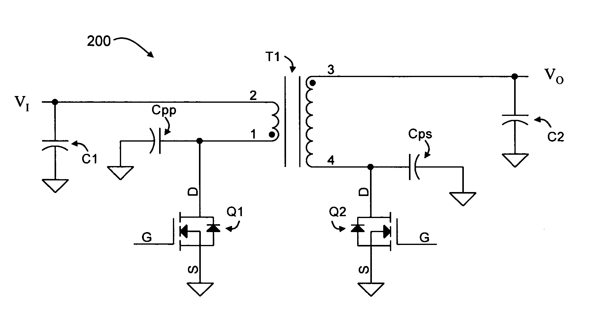
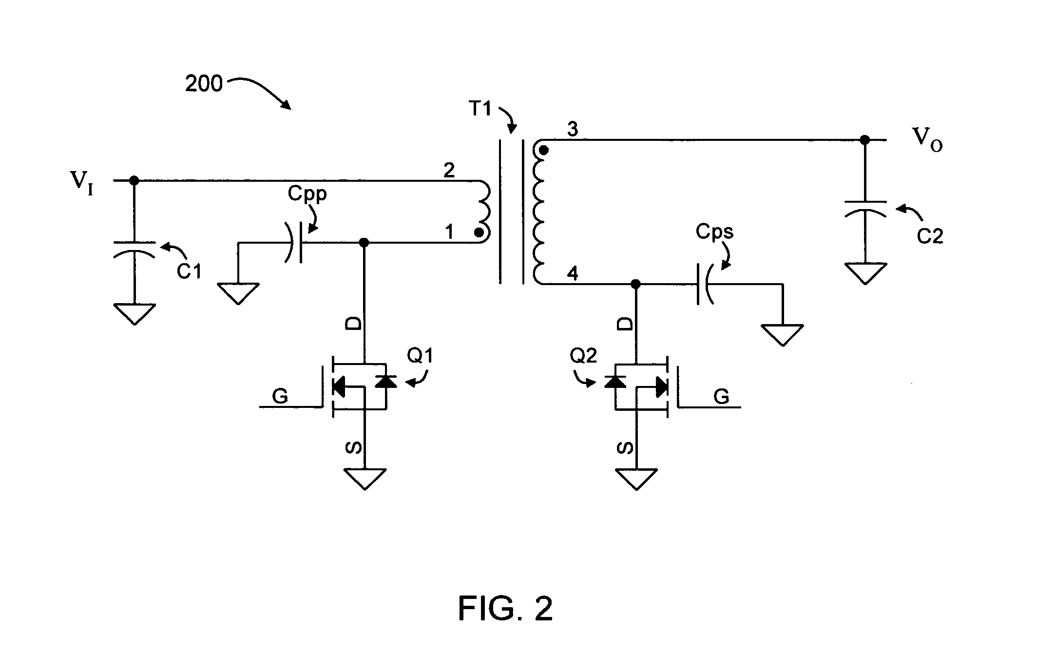
[0098] An exemplary application of the power circuit of FIG. 2 involves charging a 1 nF capacitor (C2) to 2000 V (VO) in 2.5 msec, with a 10 V input supply (VI). Using Cpp and Cps capacitors having values of 500 pF and 50 pF, respectively, and a selected switching frequency of 25 kHz. The flyback transformer (T1) may have an inductance (as measured from the primary side) of 82 uH, and a primary-to-secondary turns ratio of 1:50. Capacitor C1 may have a value of 190 uF or greater. The peak voltage across transistor Q1 is about 50V, while the worst-case peak current in transistor Q1 during the charging cycle is about 3.9 A, and the minimum current in transistor Q1 is about 25 mA. The peak voltage across transistor Q2 is about 2500 V, while the maximum and minimum currents in transistor Q2 is about 500 nA to about −78 mA, respectively.

[0099] Methods associated with the subject power and control circuits are contemplated in which those methods are carried out with high-frequency devices...


PUM


Abstract

The present the invention provides power circuitry for the charging and discharging of high-frequency devices.

Description

FIELD OF THE INVENTION [0001] The present invention is related to power circuitry for the charging and discharging of devices at high frequencies. The power circuitry of the present invention is particularly suitable for high-voltage applications, with one particular application being electroactive polymer transducer devices. BACKGROUND [0002] A tremendous variety of devices used today rely on actuators of one sort or another to convert electrical energy to mechanical energy. The actuators “give life” to these products, putting them in motion. Conversely, many power generation applications operate by converting mechanical action into electrical energy. [0003] Employed to harvest mechanical energy in this fashion, the same type of actuator may be referred to as a generator. Likewise, when the structure is employed to convert physical stimulus such as vibration or pressure into an electrical signal for measurement purposes, it may be referred to as a transducer. Yet, the term “transdu...

Claims


Application Information

Patent Timeline
IPC IPC(8): H02M3/335
CPCH02M3/33584
Inventor DRABING, RICHARD B.SENESKY, MATTHEW KURT
Owner BAYER MATERIALSCIENCE AG
Why Eureka
Try Eureka