
Method and Apparatues for Image Inspection

a technology of image inspection and apparatus, applied in the field of method and apparatus for image inspection, can solve the problems of reducing the field of view for identification and requiring considerable time, and achieve the effect of easy and fast display of results and the final display of detected image defects or the lik

Inactive Publication Date: 2007-10-04
JAPAN SCI & TECH CORP
View PDF2 Cites 18 Cited by
  • Summary
  • Abstract
  • Description
  • Claims
  • Application Information

AI Technical Summary

Benefits of technology

[0075] The invention has following advantages.
[0076] (1) According to the invention, especially differently from the conventional digital image processing operation, the novel image processing computing method is proposed and used in which the inverse Fourier transformed image is formed by using the difference in the amplitude spectrum (intensity information) between the reference image and the Fourier transformed image of the checked image and the phase spectrum (phase information) of the Fourier transformed image of the reference image, and the defect check of the checked image is performed, and accordingly, the new technique has been developed which does not require the pre-processing of positioning of images and is superior to the conventional digital image processing method.
[0077] (2) Besides, in the newly developed checking method, the information of the minute defect of the checked image is converted into the optical diffraction pattern of the minute defect obtained by the irradiation of the laser light, that is, the amplitude spectrum (intensity information) of the Fourier transformed image, and since the optical diffraction pattern of the minute object is enlarged as the size becomes small, the minute defect, the minute particle or the like can be detected in a large field of view and quickly without using an enlarged image. Accordingly, in the invention, the checking of a minute defect, a pollutant minute particle or the like on a large size pattern drawn board, the identification of which has been conventionally considerably difficult, becomes easy, and the display of the result becomes very easy and quick.
[0078] (3) Further, in the invention, even if the position of the checked board is shifted back and forth and left and right within the irradiation light flux, since the optical diffraction pattern of the checked board appears on the optical axis center of the Fourier transform lens without fail, and further, since the amplitude spectrum (intensity information) of the Fourier transformed image of the checked image appears on the screen center even if the position of the checked image is shifted back and forth and left and right within the irradiation light flux, the accurate positioning of the checked board and the like and the pre-processing of the images are not required.
[0079] (4) Furthermore, in the invention, since the suitable digital / analog hybrid image processing method is used, the processing time until the display of the check result of the defective image becomes remarkably short as compared with the related art.
[0080] (5) In addition, according to the invention, as compared with the Fourier transformed image comparison method as the optical analog identification method, it is unnecessary to use the expensive equipment such as the multiple matched filter and the high level technique, and there is a merit that as compared with the multiple matched filter method, the final display of the detected image defect or the like becomes easy and fast.
[0081] (6) Besides, in the conventional measurement optical system, the thin laser beam is irradiated to scan the measured object, and the whole surface of the measured image is checked. On the other hand, according to the invention, as the acquisition method of the sharpened image of the reference image or the checked image, the optical system different from the conventional method is adopted for both the irradiation optical system and the light receiving optical system, and accordingly, the whole surface of the checked board is irradiated with the parallel laser light flux in which the polarizing plane is adjusted and the wavelength selection of the complementary color or the like is performed, and only the suitable polarizing plane and wavelength image is received by the whole screen.
[0082] (7) The invention is superior in the method in which the check accuracy is raised and the check speed is increased.
[0083] (8) The invention is superior in that the whole of the screen is checked at the same time and in the check speed which is not in the conventional method.
[0084] (9) According to the invention, the apparatus is relatively simple in the structure, and is superior in the manufacture cost as compared with the conventional method.

Problems solved by technology

However, in the related art, there are following problems to be solved.
(1) In the method of performing the convolution of the Fourier transformed (FFT) images of the reference image and the checked image and the inverse Fourier transform (FFT) thereof for the check of the defective image of the minute lack, projection or the like in the conventional digital image processing method, there has been a problem that pre-processing of locating of the two images to be compared in the image processing is required, and a considerable time is required for that.
(2) Besides, in the conventional digital image processing method, in order to identify a very minute defect in a large size image, a comparison is made in the image recorded on the pixels of the electronic camera, and accordingly, the enlargement of the minute object is indispensable, and there has been a problem that when the enlargement is performed, the field of view for identification must be narrowed.

Method used


Image

  • Method and Apparatues for Image Inspection
  • Method and Apparatues for Image Inspection
  • Method and Apparatues for Image Inspection

Examples


first embodiment (

(1) First Embodiment (Reference Image, Identified Image)

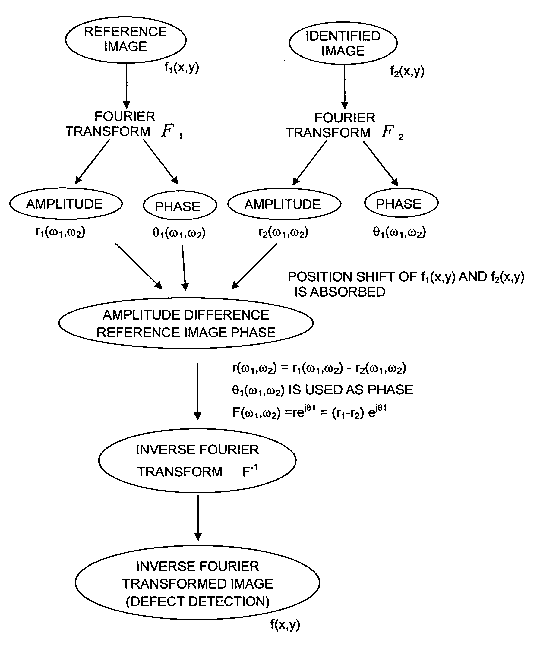
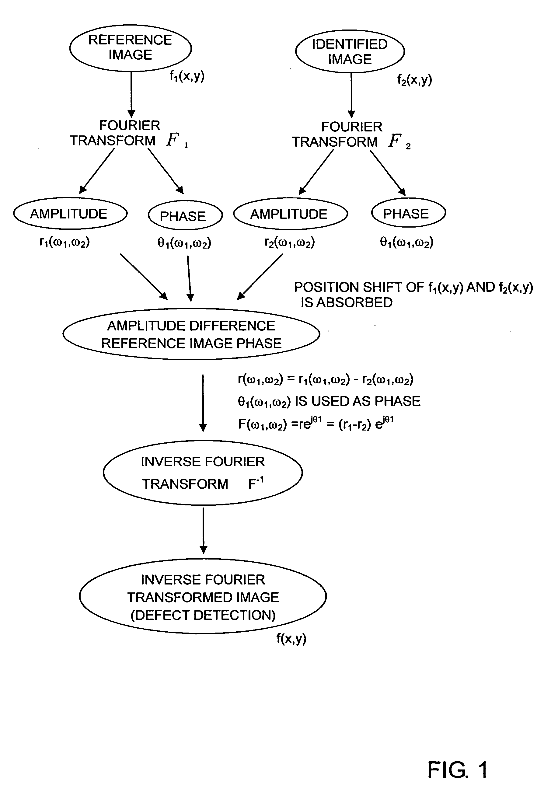
[0132]FIG. 6 is a flowchart of a first embodiment of a method for image inspection.

[0133] The computer 3 (processing part 101, the same applies hereinafter) captures a reference image from the storage part 105 or the CCD camera 2 through the interface part 106 (S101) The computer3 captures an identified image from the storage part 105 or the CCD camera 2 through the interface part 106 (S103) Incidentally, in the case where the reference image or the identified image is previously stored in the storage part 105, the computer 3 reads the data from the storage part 105 and can use it.

[0134] Next, the computer 3 judges whether or not the inputted respective images are gray scale images (S105), and converts them into gray scale images as the need arises (S107). Incidentally, in the case where gray scale data is already inputted to the computer 3 through the structure of the CCD camera or the structure of the interface part 106, th...

second embodiment (

(2) Second Embodiment (Reference Image, Fourier Transformed Image of Identified Image)

[0139]FIG. 7 shows a flowchart of a second embodiment of a method for image inspection.

[0140] The computer 3 acquires a reference image from the storage part105 or the CCD camera 2 through the interface part 106 (S101) The computer 3 acquires an amplitude spectrum (intensity information) of a Fourier transformed image of an identified image from the storage part 105 or the CCD camera 1 through the interface part 106 (S203).

[0141] Next, similarly to the first embodiment, the computer 3 executes a processing relating to the gray scale as the need arises (S105, 107).

[0142] The computer 3 Fourier transforms the reference image and obtains an amplitude spectrum (intensity information) and a phase spectrum (phase information) (S109).

[0143] Hereinafter, the computer executes processing steps S113 to S117 similar to those of the first embodiment.

third embodiment (

(3) Third Embodiment (Reference Image and its Fourier Transformed Image, Fourier Transformed Image of Identified Image)

[0144]FIG. 8 is a flowchart of a third embodiment of a method for image inspection.

[0145] The computer 3 captures a reference image from the storage part 105 or the CCD camera 2 through the interface part 106 (S101) The computer 3 acquires an amplitude spectrum (intensity information) of a Fourier transformed image of the reference image from the storage part 105 or the CCD camera 1 through the interface part 106 (S201). The computer 3 acquires an amplitude spectrum (intensity information) of a Fourier transformed image of an identified image from the storage part 105 or the CCD camera 1 through the interface part 106 (S203).

[0146] Next, similarly to the first embodiment, the computer 3 executes a processing relating to the gray scale as the need arises (S105, 107).

[0147] The computer 3 Fourier transforms the reference image and obtains a phase spectrum (phase in...


PUM


Abstract

An image checking process wherein only a defective or differential portion of a checked image is displayed together with its position and wherein no pre-processing is required for image positioning. A computer (3) captures a reference image or Fourier transformed image thereof from a storage part, a CCD camera (1) or a CCD camera (2) to acquire intensity information and phase information, and also captures an identified image or Fourier transformed image thereof from the storage part, CCD camera (1) or CCD camera (2) to acquire intensity information of the Fourier transformed image of the identified image. Then, the computer (3) determines the difference in intensity information between the reference image and the Fourier transformed image of the identified image and further determines an inverse Fourier transformed image of an expression obtained from the determined differential intensity information and the phase information of the reference image to output the inverse Fourier transformed image to an output part or display part. The inverse Fourier transformed image is used to extract, as a difference between the identified image and the reference image, an image defect of the identified image or the image difference between the identified image and the reference image.

Description

BACKGROUND OF THE INVENTION [0001] 1. Technical Field [0002] The present invention relates to a method and an apparatus for image inspection, and particularly to a method and an apparatus for image inspection for quickly performing a check of a minute defect or foreign matter on an identified image (an image to be identified, an image to be inspected, an image to be checked), a comparison, collation and check between the identified image and a reference image, or the like. [0003] 2. Background Art [0004] As conventional digital image processing methods of image defect extraction, following methods are enumerated. [0005] (1) A method of performing the convolution of Fourier transformed (FFT) images of a reference image and a checked image and the inverse Fourier transform (FFT) thereof for a check of a defective image of a minute lack, projection or the like in a conventional digital image processing method (see non-patent document 1 with respect to a position correcting method, and ...

Claims


Application Information

Patent Timeline
IPC IPC(8): G01N21/88G01N21/956G01T7/00G06T1/00G06T7/00
CPCG06T7/0002G01N21/88G06T1/00G06T7/0004
Inventor SHIMIZU, ISAO
Owner JAPAN SCI & TECH CORP
Learn More