Honeycomb filter

a filter and honeycomb technology, applied in the field of honeycomb filter, can solve the problems of large pressure loss and insufficiently minimize pressure loss, and achieve the effect of high efficiency and minimal initial pressure loss during exhaust gas treatmen

Inactive Publication Date: 2007-10-11
NGK INSULATORS LTD
View PDF11 Cites 37 Cited by
  • Summary
  • Abstract
  • Description
  • Claims
  • Application Information

AI Technical Summary

Benefits of technology

[0011]The present invention has been developed in view of such conventional technical problems, and an object of the present invention is to provide a honeycomb filter capable of minimizing an initial pressure loss during an exhaust gas treatment in a state in which a high efficiency is maintained in trapping particulate matters from an exhaust gas.
[0018]According to the honeycomb filter of the present invention, since the average pore diameter of the partition walls is 8 to 18 μm and the standard deviation in terms of common logarithm in pore diameter distribution, when pore diameters are expressed in terms of common logarithm, is 0.2 to 0.5, the initial pressure loss during the exhaust gas treatment can be minimized in a state in which the high efficiency is maintained in trapping the particulate matters.

Problems solved by technology

Moreover, the above conventional technology produces a constant effect on the trapping efficiency, but does not sufficiently minimize the pressure loss.
Especially, the pressure loss is large in an initial state of an operation before particulate matters are deposited on the DPF.

Method used


Image

  • Honeycomb filter
  • Honeycomb filter
  • Honeycomb filter

Examples


example 1

[0054]As cordierite forming materials, alumina, alumina hydroxide, kaolin, talc and silica were used. Each of the materials in which a particle size (V50) (μm) at 50 vol % was 10 μm in each volume particle size distribution was used. As the whole cordierite forming materials, in the volume particle size distribution of the whole cordierite forming material, the particle size distributions of the materials were adjusted so that a value of a ratio (a volume particle size distribution ratio: [Vall90] / [Vall10]) of a particle size (Vall0) (μm) at 90 vol % to a particle size (Vall10) (μm) at 10 vol % was 7.

[0055]To 100 parts by mass of the cordierite forming material, 35 parts by mass of water as a dispersion medium, 6 parts by mass of organic binder and 0.5 part by mass of dispersant were added, mixed and kneaded to prepare a clay. A coke was used as a pore former, hydroxypropyl methyl cellulose was used as an organic binder and ethylene glycol was used as a dispersant. The pore former h...

example 2

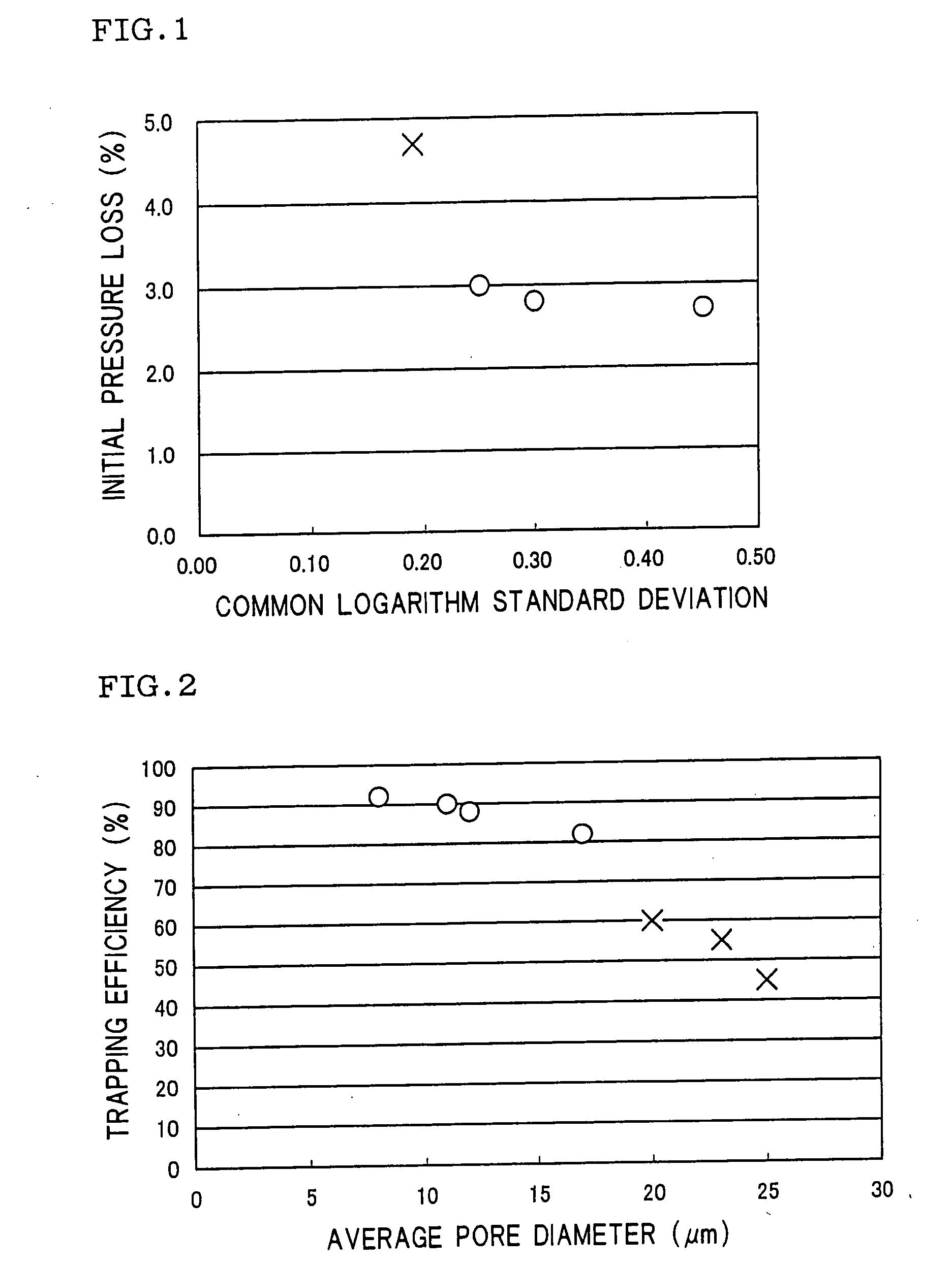
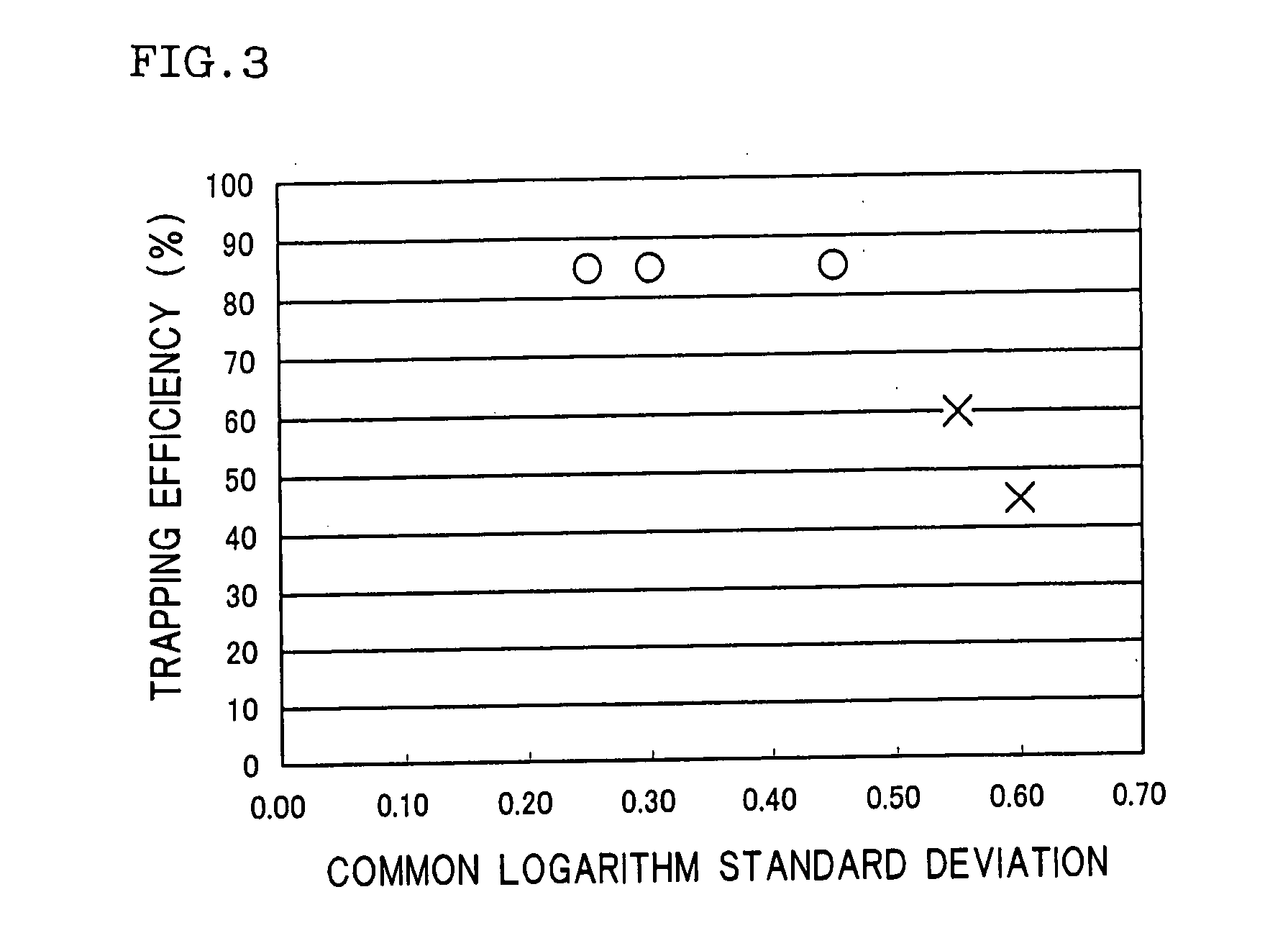
[0071]A honeycomb filter (Example 2) was prepared in the same manner as in Example 1 except that a particle diameter distribution of a pore former, an amount of the pore former to be blended and a particle diameter distribution of a cordierite forming material were appropriately controlled to thereby set a standard deviation in terms of common logarithm to 0.3. An average pore diameter and a standard deviation in terms of common logarithm in pore diameter distribution were measured, and an initial trapping efficiency (the trapping efficiency) and an initial pressure loss during an exhaust gas treatment were measured in the same manner as in Example 1. Results are shown in Table 1.

example 3

[0072]A honeycomb filter (Example 3) was prepared in the same manner as in Example 1 except that a particle diameter distribution of a pore former, an amount of the pore former to be blended and a particle diameter distribution of a cordierite forming material were appropriately controlled to thereby set a standard deviation in terms of common logarithm to 0.45. An average pore diameter and a standard deviation in terms of common logarithm in pore diameter distribution were measured, and an initial trapping efficiency (the trapping efficiency) and an initial pressure loss during an exhaust gas treatment were measured in the same manner as in Example 1. Results are shown in Table 1.


PUM

PropertyMeasurementUnit
pore diameter distributionaaaaaaaaaa
pore diameteraaaaaaaaaa
thicknessaaaaaaaaaa

Abstract

There is disclosed a honeycomb filter capable of minimizing an initial pressure loss during an exhaust gas treatment in a state in which a high efficiency is maintained in trapping particulate matters included in an exhaust gas. In the honeycomb filter which includes porous partition walls to define and form a plurality of cells constituting channels of a fluid and in which the predetermined cells each opened at one end thereof and plugged at the other end thereof and the remaining cells each plugged at one end thereof and opened at the other end thereof are alternately arranged, an average pore diameter of the partition walls is in a range of 8 to 18 μm, and a standard deviation in terms of common logarithm in pore diameter distribution, when pore diameters are expressed in terms of common logarithm, is in a range of 0.2 to 0.5.

Description

BACKGROUND OF THE INVENTION[0001]1. Field of the Invention[0002]The present invention relates to a honeycomb filter. The present invention more particularly relates to a honeycomb filter capable of minimizing an initial pressure loss during an exhaust gas treatment in a state in which a high efficiency is maintained in trapping particulate matters included in an exhaust gas.[0003]2. Description of the Related Art[0004]In consideration of influences on environments, there is a rising necessity to remove, from an exhaust gas, particulate matters and harmful substances included in the exhaust gas discharged from combustion devices including internal combustion engines such as an engine for a car, an engine for a construction machine and a fixed engine for an industrial machine. Especially, regulations with regard to removal of the particulate matters (hereinafter sometimes referred to as the “PMs”) discharged from a diesel engine tend to be tightened globally, use of a honeycomb filter...

Claims


Application Information

Patent Timeline
Patent Type & Authority Applications(United States)
IPC IPC(8): B01D39/20
CPCB01D46/2429B01D46/2466B01D46/2474B01D2046/2437B01D2046/2496Y02T10/20C04B38/0009C04B2111/00793F01N3/0222F01N2330/06F01N2330/30B01D2279/30C04B35/10C04B35/14C04B35/185C04B35/195C04B35/447C04B35/46C04B35/48C04B35/565C04B35/597C04B38/0054C04B38/007Y02T10/12B01D46/2498B01D46/24492B01D46/2482
Inventor MIYAIRI, YUKIONOGUCHI, YASUSHINAKANE, YUKARI
Owner NGK INSULATORS LTD
Why Eureka
Try Eureka