Tubular radiation absorbing device for a solar power plant with reduced heat losses

a solar power plant and tube technology, applied in the safety of solar heat collectors, solar heat systems, lighting and heating apparatuses, etc., can solve the problems of increased heat loss, undesirable pressure fluctuations, and reduced efficiency of tubular radiation absorption devices

Inactive Publication Date: 2007-10-11
ALLEGIANCE CORP +1
View PDF14 Cites 22 Cited by
  • Summary
  • Abstract
  • Description
  • Claims
  • Application Information

AI Technical Summary

Benefits of technology

[0023] Preferably the ratio VA=H2 / H2O of the steam for treating the outer side of the central tube is greater than the ratio V1=H2 / H2O of the steam for treating the inner side of the central tube. The formation of the spinel layer on the outer side is avoided by these process steps.

Problems solved by technology

This pressure increase leads to increased heat losses and to a reduced efficiency of the tubular radiation absorbing device.
This arrangement has the disadvantage that the strip is in a region, which can be exposed to direct radiation.
Because the getter material with a predetermined loading degree has a temperature dependent equilibrium pressure (equilibrium between gas desorption and adsorption), temperature fluctuations of the getter material lead to undesirable pressure fluctuations.
The temperature of the tubular jacket greatly increases after consumption of the getter material and the absorber tube becomes unusable.

Method used


Image

  • Tubular radiation absorbing device for a solar power plant with reduced heat losses
  • Tubular radiation absorbing device for a solar power plant with reduced heat losses

Examples


Embodiment Construction

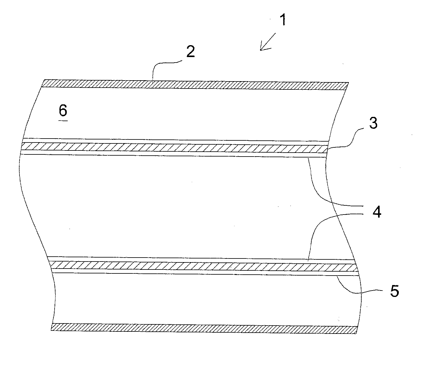
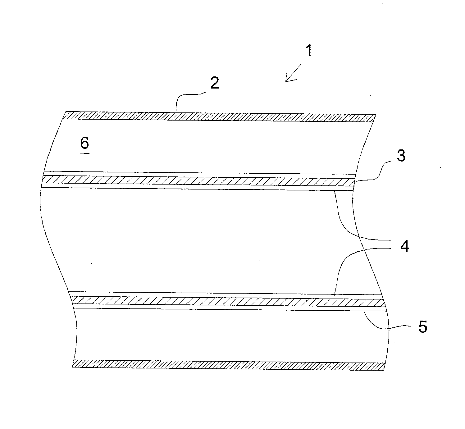
[0030] A tubular radiation absorbing device 1 for solar thermal applications is shown in the cross-sectional view in the sole FIGURE. The tubular radiation absorbing device 1 comprises a central tube 3 made of metal and, a glass tubular jacket 2 surrounding the central tube so that a ring-shaped space 6 is formed between the tubular jacket and the central tube.

[0031] A heat carrier medium, which contains free hydrogen, flows through the central tube 3, which is made of metal. The hydrogen can permeate metal and thus pass through the central tube 3 into the ring-shaped space 6. In order to prevent the free hydrogen from passing through the central tube 3, which e.g. is made from Chromium-Nickel-Molybdenum 17-12-2 Steel No. 1.4404, it is provided with a barrier coating 4 on its interior side, which contains Cr2O3.

[0032] The inner coating 4 has a thickness of e.g. 10 μm. The coating 4 comprises a first layer and a further or second layer applied to the first layer. The first layer co...


PUM


Abstract

The tubular radiation absorbing device (1) for solar thermal applications includes a central tube (3) made of chromium steel, particularly stainless steel; a glass tubular jacket (2) surrounding the central tube so as to form a ring-shaped space (6); and a barrier coating (4) on at least an interior side of the central tube (3), which is substantially impermeable to hydrogen and contains chromium oxide. The barrier coating (4) is provided by a process in which the central tube (3) is treated with steam containing free hydrogen at a temperature of 500° C. to 700° C.

Description

CROSS-REFERENCE [0001] The invention described and claimed hereinbelow is also described in German Patent Application 10 2005 057 277.4-15, filed Nov. 25, 2005 in Germany, which provides the basis for a claim of priority under 35 U.S.C. 119. BACKGROUND OF THE INVENTION [0002] 1. Field of the Invention [0003] The present invention relates to a tubular radiation absorbing device for solar thermal applications, especially for a parabolic trough collector in a solar power plant, which comprises a central tube made from a chromium steel, especially stainless steel, and a glass tubular jacket surrounding the central tube so as to form a ring-shaped space between the tubular jacket and the central tube. [0004] 2. Related Art [0005] Tubular radiation absorbing devices or absorber pipes are used in parabolic trough collectors to utilize solar radiation. The solar radiation is concentrated by a tracking mirror on a tubular radiation absorbing device and converted into heat. The heat is conduc...

Claims


Application Information

Patent Timeline
Patent Type & Authority Applications(United States)
IPC IPC(8): F24J2/50F24S10/40F24S20/20
CPCF24J2/055F24J2/07Y02E10/44F24J2/4616Y02E10/41F24J2/4612F24S20/20F24S40/46F24S40/40F24S10/45F24S10/00Y02E10/40
Inventor KUCKELKORN, THOMASBENZ, NIKOLAUS
Owner ALLEGIANCE CORP
Why Eureka
Try Eureka