Reduced contaminant gas injection system and method of using

a gas injection system and gas distribution system technology, applied in the direction of electric discharge tubes, coatings, chemical vapor deposition coatings, etc., can solve the problems of harsh environment for the interior surfaces of the processing chamber, reduce the yield during the fabrication of integrated circuits, etc., and achieve the effect of minimizing contamination to the substra

Inactive Publication Date: 2007-10-11
TOKYO ELECTRON LTD
View PDF6 Cites 81 Cited by
  • Summary
  • Abstract
  • Description
  • Claims
  • Application Information

AI Technical Summary

Benefits of technology

[0009]According to one embodiment, a treatment system is described for performing an etch process on a substrate using a corrosive gas, whereby a gas distribution system for dispersing the corrosive gas is designed to uniformly distribute process gas above the substrate while minimizing contamination to the substrate.

Problems solved by technology

While the process gas chemistry is selected to facilitate the etch process at the substrate surface, it poses a harsh environment for the interior surfaces of the processing chamber.
The process gas can include corrosive gases that may be detrimental to components of the processing chamber, and may lead to the contamination of the substrate, hence reducing yield during the fabrication of integrated circuits (ICs)

Method used


Image

  • Reduced contaminant gas injection system and method of using
  • Reduced contaminant gas injection system and method of using
  • Reduced contaminant gas injection system and method of using

Examples


Embodiment Construction

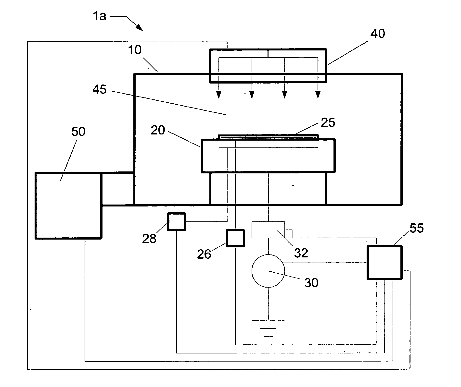
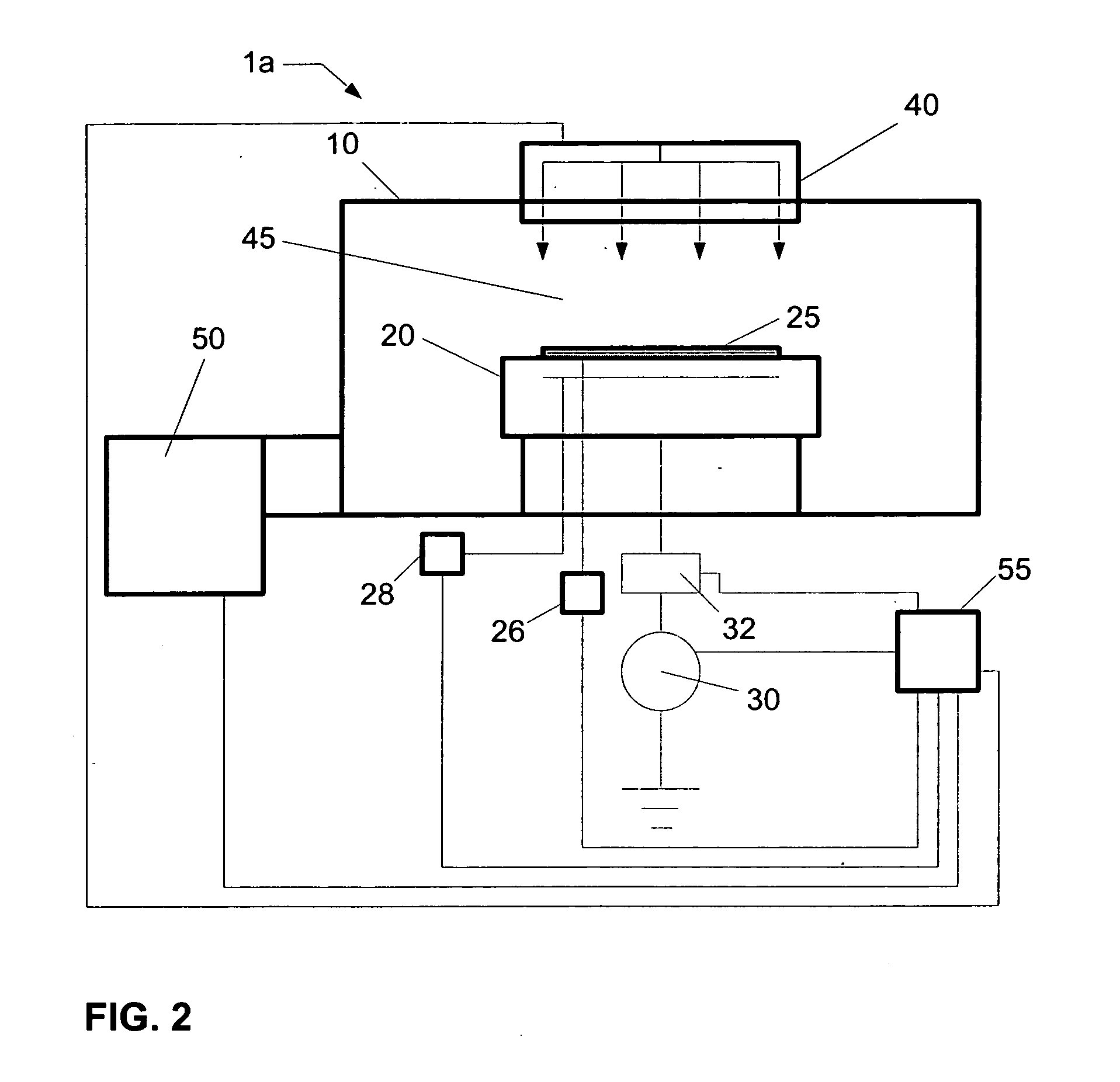
[0020]In the following description, purposes of explanation and not limitation, specific details are set forth, such as a particular geometry of the vacuum or plasma processing system and descriptions of various components. However, it should be understood that the invention may be practiced in other embodiments that depart from these specific details.

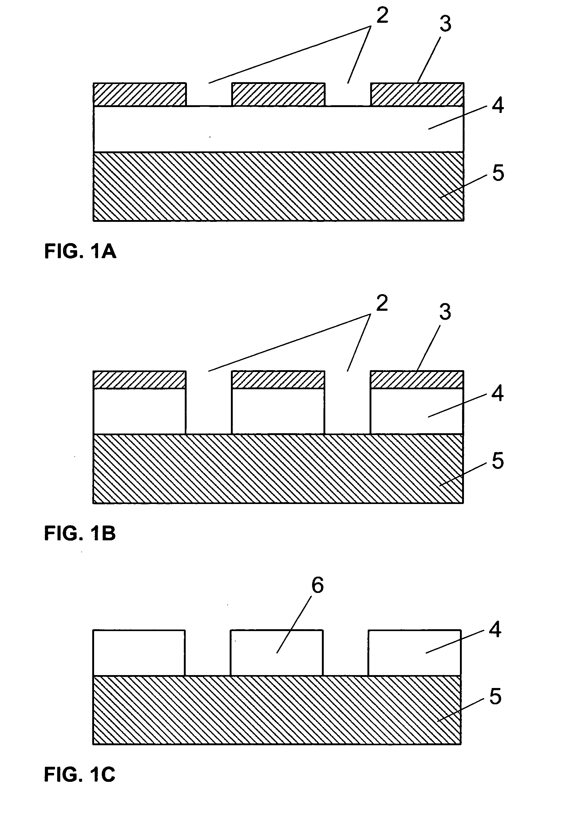
[0021]In material processing methodologies, pattern etching comprises the application of a thin layer of light-sensitive material, such as photoresist, to an upper surface of a substrate, that is subsequently patterned in order to provide a mask for transferring this pattern to the underlying material during etching. The patterning of the light-sensitive material generally involves exposure by a radiation source through a reticle (and associated optics) of the light-sensitive material using, for example, a micro-lithography system, followed by the removal of the irradiated regions of the light-sensitive material (as in the case of posi...


PUM

PropertyMeasurementUnit
half angleaaaaaaaaaa

Abstract

A gas injection system includes a diffuser to distribute a process gas in a processing chamber. The gas injection system may be utilized in a polysilicon etching system involving corrosive process gases.

Description

BACKGROUND OF THE INVENTION[0001]1. Field of Invention[0002]The present invention relates to a gas distribution system for a vacuum processing system, and more particularly to a gas distribution system for introducing a process gas in a vacuum processing system.[0003]2. Description of Related Art[0004]During semiconductor processing, a (dry) plasma etch process can be utilized to remove or etch material along fine lines or within vias or contacts patterned on a silicon substrate. The plasma etch process generally involves positioning a semiconductor substrate with an overlying patterned, protective mask layer, for example a photoresist layer, in a processing chamber.[0005]Once the substrate is positioned within the chamber, an ionizable, dissociative gas mixture is introduced within the chamber at a pre-specified flow rate, while a vacuum pump is throttled to achieve an ambient process pressure. Thereafter, a plasma is formed when a fraction of the gas species present are ionized by...

Claims


Application Information

Patent Timeline
Patent Type & Authority Applications(United States)
IPC IPC(8): H01L21/306C23F1/00
CPCH01J37/3244H01J37/32449H01L21/67069H01L21/32137H01L21/32136C23C16/455H01L21/205
Inventor ENOMOTO, TAKASHIHAGIHARA, MASAAKIKO, AKITERUHAMAMOTO, SHINJIURAKAWA, MASAFUMILAFLAMME, ARTHUR H.HELLER, EDWARD
Owner TOKYO ELECTRON LTD
Why Eureka
Try Eureka