High magnetic field ohmically decoupled non-contact technology

a magnetic field and non-contact technology, applied in the direction of electric/magnetic/electromagnetic heating, induction heating, electrical equipment, etc., can solve the problems of limited temperature range of ultrasonic transducers, unsatisfactory chemical interactions, and limit the energy transfer

Inactive Publication Date: 2007-10-11
UT BATTELLE LLC
View PDF3 Cites 29 Cited by
  • Summary
  • Abstract
  • Description
  • Claims
  • Application Information

AI Technical Summary

Benefits of technology

[0009]According to an embodiment of the invention, a process comprises: applying a high magnetic field to at least a portion of a conductive material; and applying an inductive magnetic field to at least a fraction of the conductive material to induce a surface current within the fraction of the conductive material, the surface current generating a substantially bi-directional force that defines a vibration, characterized in that i) the high magnetic field and the inductive magnetic field are substantially confocal, ii) the fraction of the conductive material is located within the portion of the conductive material and iii) ohmic heating from the surface current is ohmically decoupled from the vibration. According to another embodiment of the invention, a machine comprises: a high magnetic field coil defining an applied high magnetic field; an inductive magnetic field coil coupled to the high magnetic field coil, the inductive magnetic field coil defining an applied inductive magnetic field; and a processing zone located within both the applied high magnetic field and the applied inductive magnetic field, characterized in that i) the high magnetic field and the inductive magnetic field are substantially confocal, and ii) ohmic heating of a conductive material located in the processing zone is ohmically decoupled from a vibration of the conductive material.

Problems solved by technology

Commercially available ultrasonic processing systems require direct contact with the melt, resulting in undesirable chemical interactions when the acoustic probe / horn is inserted directly into the molten material or in direct contact with the containment vessel such as a crucible or mold.
Ultrasonic transducers are limited in temperature range, and therefore must be thermally isolated from high-temperature environments through the use of an acoustical waveguide, or horn.
Acoustic impedance mismatches between the transducer and the waveguide, as well as between the waveguide and the melt can limit the transfer of energy.
In addition, the localized nature of the horn probe results in a very non-uniform distribution of acoustical energy within the melt crucible.

Method used


Image

  • High magnetic field ohmically decoupled non-contact technology
  • High magnetic field ohmically decoupled non-contact technology
  • High magnetic field ohmically decoupled non-contact technology

Examples


example 1

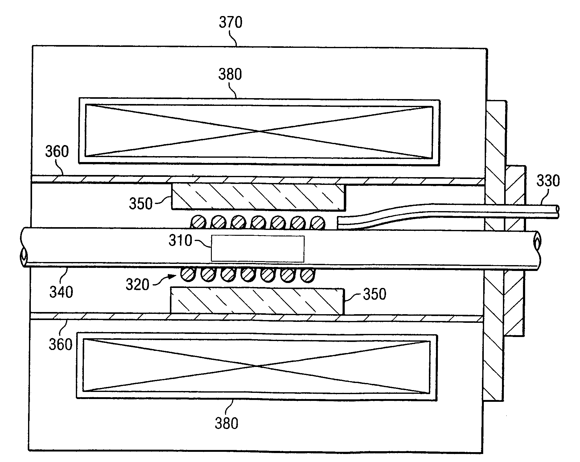
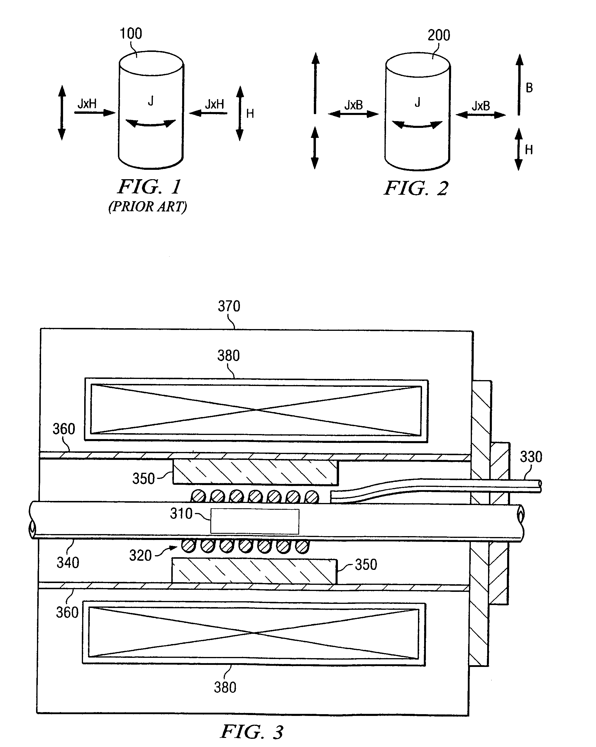
[0045]An embodiment of a non-contact, ultrasonic, ohmically decoupled insert inside a nine Tesla superconducting magnet is shown in FIG. 3. The work piece 310 is shown inside a single induction coil 320. The coil 320 includes a single layer of water-cooled copper tubing. Power is fed to the coil by way of a coaxial transmission line 330. The work piece 310 is electrically and thermally insulated from the induction coil 320 by a quartz tube 340. Ceramic spacers 350 support the induction coil against electromagnetic forces. An actively cooled conductive lining 360 is placed between the induction coil and the bore of the cryostat to prevent heat loading of the cryogenic system 370 of the superconducting magnet 380. Some electromagnetic energy is deposited in the lining. This particular embodiment includes a superconducting magnet including of niobium-titanium conductors that are readily commercially supplied by American Magnetics, Inc.

example 2

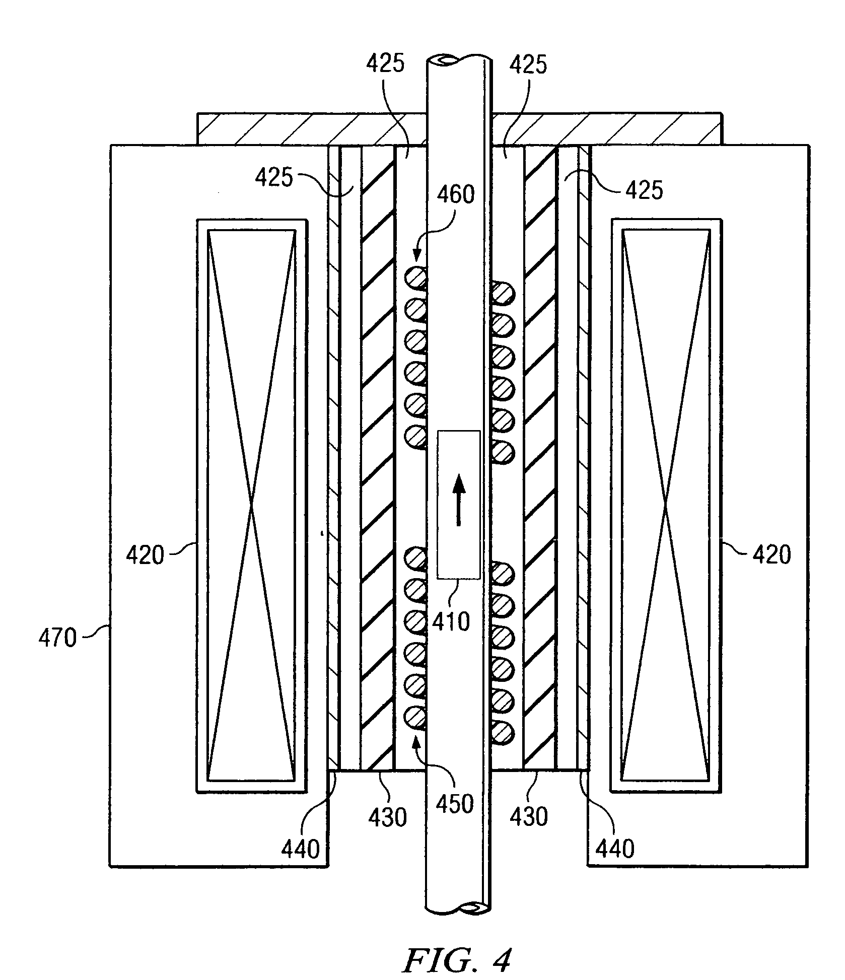
[0046]An embodiment for continuous work piece processing is shown in FIG. 4. A continuous work piece 410 passes coaxially through a super conducting solenoid magnet assembly 420. This embodiment also illustrates a dual coil configuration. One coil 450 is optimized for inductive heating of the work piece. The other coil 460 is optimized for application of ultrasonic excitation. Thermal insulation 430 is used to minimize the heat load on the superconducting magnet's cryostat 470. There are spaces 425 for cooling gases between the work piece 410 and the thermal insulation 430 and also between the thermal insulation 430 and a conductive electromagnetic barrier 440.

example 3

[0047]An embodiment is shown in FIG. 5 that heats a work piece 510 by a heated gas from a hot gas work piece heating system 520 via a gas distribution nozzle 530 while ultrasonic energy is applied through an induction coil 540 that is water or gas cooled. This embodiment illustrates another method of separating heating and ultrasonic processing functions. Thermal insulation 580 is used to minimize the heat load on the magnet 590. There are spaces 560 for cooling gases between the work piece 510 and the thermal insulation 580 and also between the thermal insulation 580 and a conductive electromagnetic barrier 570.


PUM


Abstract

Methods and apparatus are described for high magnetic field ohmically decoupled non-contact treatment of conductive materials in a high magnetic field. A method includes applying a high magnetic field to at least a portion of a conductive material; and applying an inductive magnetic field to at least a fraction of the conductive material to induce a surface current within the fraction of the conductive material, the surface current generating a substantially bi-directional force that defines a vibration. The high magnetic field and the inductive magnetic field are substantially confocal, the fraction of the conductive material is located within the portion of the conductive material and ohmic heating from the surface current is ohmically decoupled from the vibration. An apparatus includes a high magnetic field coil defining an applied high magnetic field; an inductive magnetic field coil coupled to the high magnetic field coil, the inductive magnetic field coil defining an applied inductive magnetic field; and a processing zone located within both the applied high magnetic field and the applied inductive magnetic field. The high magnetic field and the inductive magnetic field are substantially confocal, and ohmic heating of a conductive material located in the processing zone is ohmically decoupled from a vibration of the conductive material.

Description

STATEMENT AS TO RIGHTS TO INVENTIONS MADE UNDER FEDERALLY-SPONSORED RESEARCH OR DEVELOPMENT[0001]This invention was made with United States Government support under prime contract No. DE-AC05-00OR22725 to UT-Battelle, L.L.C. awarded by the Department of Energy. The Government has certain rights in this invention.BACKGROUND INFORMATION[0002]1. Field of the Invention[0003]Embodiments of the invention relate generally to the field of high magnetic field ohmically decoupled non-contact technology. More particularly, some embodiments of the invention relate to methods and apparatus for ohmically decoupled non-contact ultrasonic treatment of conductive materials via inductively induced surface current(s) in a static high magnetic field.[0004]2. Discussion of the Related Art[0005]Ultrasonic processing of materials in both the melt and solid phase is proving to be highly beneficial to material properties of metallic alloys. In the melt phase, acoustic treatment can be used to enhance diffus...

Claims


Application Information

Patent Timeline
Patent Type & Authority Applications(United States)
IPC IPC(8): H05B6/10
CPCH05B2214/04H05B6/101
Inventor WILGEN, JOHNKISNER, ROGERLUDTKA, GERARDLUDTKA, GAILJARAMILLO, ROGER
Owner UT BATTELLE LLC
Why Eureka
Try Eureka