Vehicle alternator

a technology of vehicle alternator and alternator, which is applied in the direction of cooling/ventilation arrangement, magnetic circuit rotating parts, and shape/form/construction of magnetic circuits, etc. it can solve the problems of increasing the space available for mounting two different vehicle alternators within the vehicle engine compartment, increasing the difficulty of solving various difficult problems, and reducing the length of the vehicle alternator. , to achieve the effect of reducing the amount of magnetic flux leakage, reducing the length of the vehicle alternator, and reducing the amount of the magnetic flux leak

Inactive Publication Date: 2007-10-11
DENSO CORP
View PDF9 Cites 24 Cited by
  • Summary
  • Abstract
  • Description
  • Claims
  • Application Information

AI Technical Summary

Benefits of technology

[0039]Even if the length of the Lundel type field iron core is reduced in the axis direction, the effect to reduce the entire length of the vehicle alternator is limited when the length of the coil end of the armature is long in the axis direction like the length of a coil end of a conventional vehicle alternator. In order to avoid this drawback, the present invention adopts the coil end of a shorter length in the axis direction composed of the plural letter-U-shaped electrical conductors. This configuration can realize reducing both of the length of the Lundel type field iron core in the axis direction and the length of the armature in the axis direction simultaneously, and as a result, it is possible to reduce the entire length of the vehicle alternator in the axis direction.
[0040]In accordance with another aspect of the present invention, there is provided the vehicle alternator in which each permanent magnet is placed extending toward the outside of the inside disk part in the radius direction. It is thereby possible to efficiently reduce the magnetic flux leakage between the inside disk part and the front end tip part of the claw poles extending to the outside area of the inside disk part in the radius direction.
[0041]In accordance with another aspect of the present invention, there is provided the vehicle alternator in which a center position of the outside disk part as the other disk part in a pair of the disk parts is within a width of the cylindrical armature iron core observed from the axial direction of the cylindrical armature iron core. It is thereby possible to increase twice or more the reduction effect of the Lundel type field iron core in the axis direction.
[0042]In accordance with another aspect of the present invention, it is so formed that a width of a front tip end surface of each tooth along the circumferential direction at the inside of the cylindrical armature iron core in the radius direction is narrower than a width of the permanent magnet along the circumferential direction. This configuration enables to reduce the amount of the magnetic flux leakage at a front tooth in which the magnetic flux flows out through the front end tip part of the tooth at the radius direction when the front tip end surface of each tooth of the armature iron core at the inside in the radius direction intersects the placement area of the permanent magnets in the circumference direction, and thereby increase the output of the vehicle alternator by the amount of the magnetic flux leakage.
[0043]In accordance with another aspect of the present invention, there is provided the vehicle alternator in which each phase has a plurality of the slots in the cylindrical armature iron core. This configuration enables to reduce the magnetic resistance of the magnet circuit of the armature iron core and also to keep the amount of magnetic saturation of the armature iron core because the number of slots per pole and per phase, in other words, the number of teeth per pole and per phase is increased even if the front end tip surface of each tooth at the inside in the radius direction of the armature. As a result, it is possible to prevent the decrease of the output caused by increasing the amount of the magnetic resistance in the magnet circuit of the armature side.
[0044]In accordance with another aspect of the present invention, there is provided the vehicle alternator in which plural line-shaped concave grooves are formed at a specified pitch on an outer circumferential surface of each claw pole. This configuration enables to reduce the amount of an eddy current generated at the front end tip surface of each claw pole at the inside of the radius direction. It is preferred that the depth of each line-shaped concave groove has a depth narrower than the gap length between the stator core (as the armature iron core) and the claw poles. It is also preferred to form the line-shaped concave grooves at a specified pitch that is smaller than the width of the tooth of the stator core in the circumferential direction at the most inside area in the radius direction. The line-shaped concave grooves are formed in the direction so as to extend the eddy current path generated in the surface of each claw pole according to the change of the magnetic flux of the teeth of the armature iron core. This can increase the output of the vehicle alternator. That is, it is possible to effectively prevent the eddy current loss at the front tip end part of the teeth at the inside in the radius direction of the armature to be caused by the additional permanent magnets and by increasing the number of the teeth. It is thereby possible to prevent the temperature rise of the field coils.

Problems solved by technology

As a result, there is increasingly less space available for mounting vehicle alternators within vehicle engine compartments.
However, it is difficult to mount the two different vehicle alternators, in particular, horizontal vehicle alternators to be placed horizontally, on a space closed to the engine of the vehicle in view of the allowance of deformation caused by crash accident.
However, the tandem vehicle alternator of such a conventional configuration has a problem of interacting the vehicle alternator with a lateral exhaust pipe and an inlet pipe mounted near the vehicle alternator because the tandem vehicle alternator has an extended effective length in a longitudinal direction thereof when compared with the size of an ordinary vehicle alternator.
Thus, there are various difficult problems to be solved for adapting the tandem vehicle alternator to various applications.
That is, even if the total length of a pair of the armatures is reduced in the axis direction by using the sequential segment joining type stator coils, it is still difficult to reduce the length of the tandem vehicle alternator in the axis direction unless the length of the rotor structure is reduced in the axis direction.
That is, even if the total length of a pair of the armatures is reduced by using the sequential segment joining type stator coils, it is still difficult to reduce the total length of the tandem vehicle alternator in the axis direction because of the difficulty of reducing the length of the rotor structure in the axis direction.
The conventional tandem vehicle alternator further involves various problems because of the close arrangement of a pair of the armatures in the axis direction.
A first problem is difficulty of supplying cooling air to a pair of coil ends (also referred to as “an inner side coil end) extended and faced to each other, namely, closely placed between a pair of armature iron cores.
This causes a temperature rise of the coil ends.
On the contrary, in the conventional tandem vehicle alternator, it is difficult to place cooling funs capable of cooling the inner coil end placed at the inner part in the radius direction and also difficult to supply the cooling air to the inner coil end.
A second problem is that a three-phase AC current is induced in one armature coil wound on a pair of the armature iron cores by a three-phase AC current flowing through the other armature coil because of an inductance generated between the both inner coil ends in a pair of the stators that are closely placed to each other.
This induced three-phase AC current deteriorates the independent controlling of each electric power generation unit.

Method used


Image

  • Vehicle alternator
  • Vehicle alternator
  • Vehicle alternator

Examples


first embodiment

(Entire Configuration)

[0059]A description will be given of the configuration and action of the segment coil type tandem vehicle alternator according to the first embodiment with reference to FIG. 1.

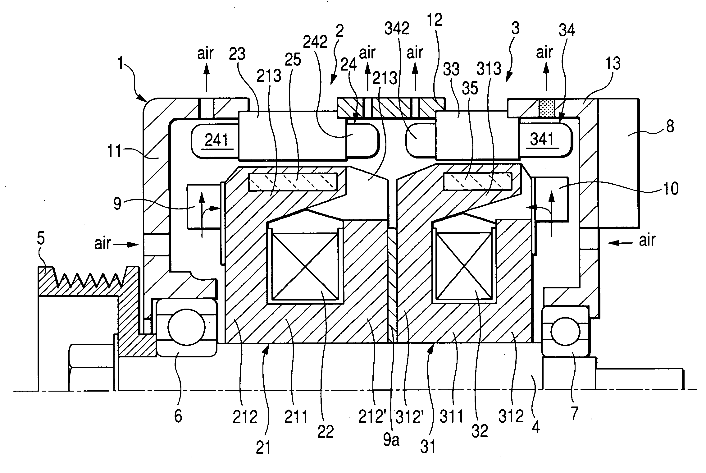
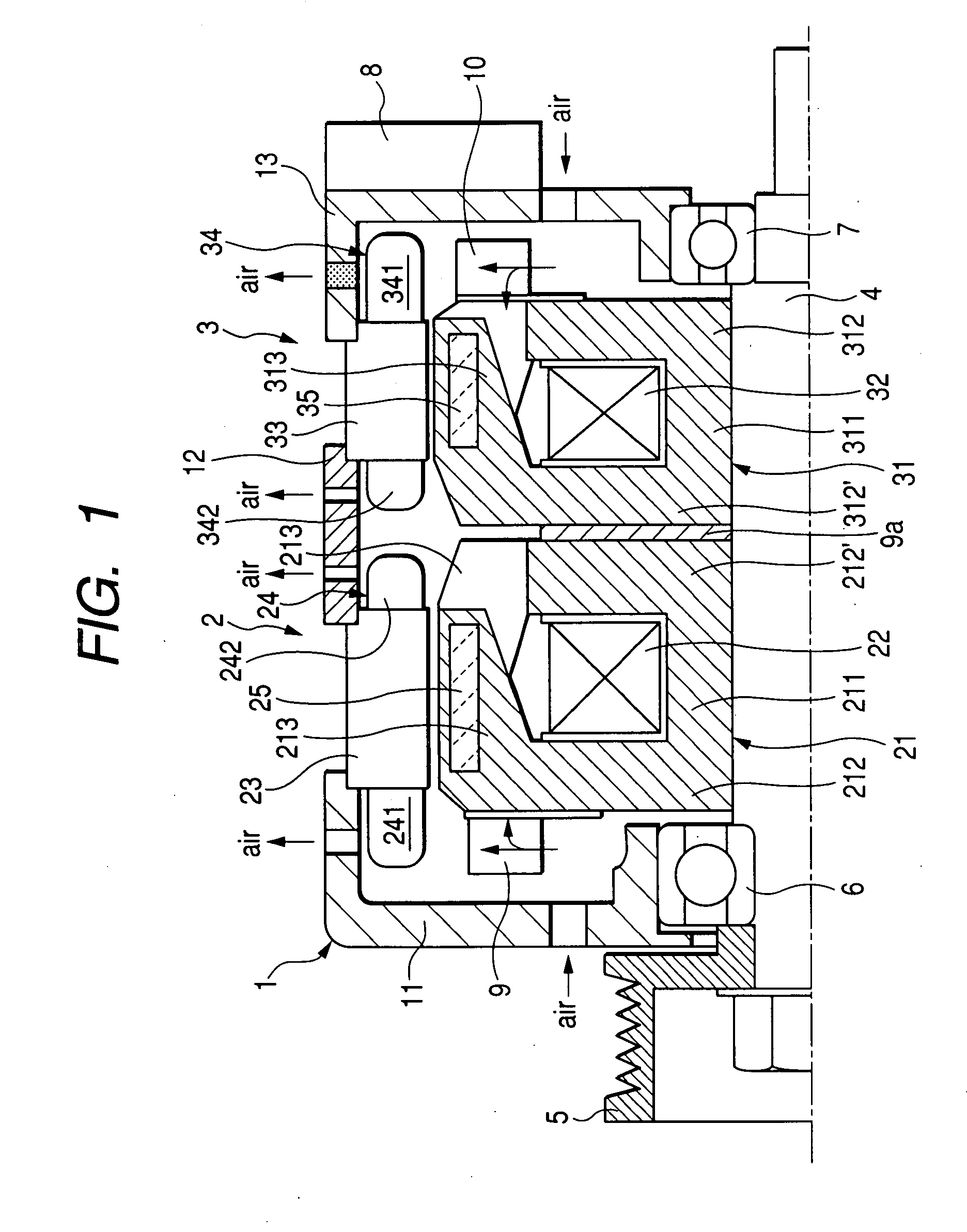
[0060]FIG. 1 is a sectional view showing a configuration of the tandem vehicle alternator having dual electric power generation units placed in an axis direction according to the first embodiment of the present invention.

[0061]The tandem vehicle alternator shown in FIG. 1 has a housing 1, a primary rotary electric machine section 2, a secondary rotary electric machine section 3, a rotor shaft 4, a pulley 5, bearings 6 and 7, a circuit device 8 composed of various apparatus such as a rectifier and a regulator, a front side cooling fan 9, and a rear side cooling fan 10.

[0062]The housing 1 is composed of a front housing 11, a center housing 12, and a rear housing 13. Those housing components 11, 12, and 13 of the housing 1 are fixed tightly together by through bolts (not shown).

[0063]The rot...

second embodiment

[0106]A description will be given of the configuration and the feature of the tandem vehicle alternator according to the second embodiment of the present invention with reference to FIG. 8 and FIG. 9.

[0107]FIG. 8 is a schematic sectional view of the vehicle alternator equipped with a single electric power generation unit composed mainly of a Lundel type rotor core and an armature according to the second embodiment of the present invention. FIG. 9 is a partial extended elevation of the Lundel rotor core observed from the direction toward the center point of the Lundel rotor core shown in FIG. 8.

[0108]The vehicle alternator according to the second embodiment has the single electric power generation unit that is different in configuration from the tandem vehicle alternator having a pair of the electric power generation units of the first embodiment shown in FIG. 1.

[0109]The first feature of the vehicle alternator according to the second embodiment is that the center position C11 of one...


PUM


Abstract

A tandem vehicle alternator has dual electrical power generation units. Each generation unit has a Lundel type rotor core and a stator coil. The Lundel type rotor cores are arranged in a tandem arrangement in the vehicle alternator. Each stator coil is composed of sequential segment joining type stator coils. A center position of an inside disk part in a pair of disk parts, placed at the outside of the rotor core, is positioned within a width of an armature iron core as a stator core. This configuration enlarges a gap between inner coil ends faced to each other in the adjacent stator coils at the inside in the axis direction, cools those inner coil ends, and reduces a mutual inductance generated between the inner coil ends. The feature improves the output of the vehicle alternator and enhances the independent control of each generation unit.

Description

CROSS-REFERENCE TO RELATED APPLICATIONS[0001]This application is related to and claims priority from Japanese Patent Application No. 2006-107580 filed on Apr. 10, 2006, the contents of which are hereby incorporated by reference.BACKGROUND OF THE INVENTION[0002]1. Field of the Invention[0003]The present invention relates to a vehicle alternator or a vehicular AC electric generator with improved installation capability for a vehicle.[0004]2. Description of the Related Art[0005]Generally, vehicles are being designed with smaller engine compartments in order to provide greater interior space. As a result, there is increasingly less space available for mounting vehicle alternators within vehicle engine compartments. The demand for increasingly higher power outputs of vehicle alternators are increasingly greater because of the increased electrical loads created by controllers of safety features and plural electrical loads. A small high-power and low-cost vehicle alternator is in great dem...

Claims


Application Information

Patent Timeline
Patent Type & Authority Applications(United States)
IPC IPC(8): H02K16/02H02K1/22
CPCH02K9/06H02K16/00H02K3/24H02K21/044H02K19/22
Inventor KUSASE, SHINSHICHIJOH, AKIYA
Owner DENSO CORP
Why Eureka
Try Eureka