Method of making integrated stator, brushless direct-current motor of radial core type double rotor structure using the integrated stator, and method of making the same

Inactive Publication Date: 2007-10-11
AMOTECH
View PDF8 Cites 57 Cited by
  • Summary
  • Abstract
  • Description
  • Claims
  • Application Information

AI Technical Summary

Benefits of technology

[0050]As described above, the present invention employs a double rotor structure in a radial core type BLDC motor, in which a number of division type core assemblies are automatically positioned and fixed, using a positioning structure formed in a mold itself when a stator core is perfectly divided into divided cores, and then is injection-molded by an insert molding method using a thermosetting resin, to thereby assemble a number of divided cores without using a separate core support plate and thus greatly enhance an assembly productivity.
[0051]In addition, in the double rotor structure of the present invention, a cooling hole is formed to have a cross-sectional area as wide as possible, vertically to the circumferential direction of a rotor supporter and a rib which connect inner and outer rotors and bushings, and a change in the size of the cooling hole is alternately given by design, to thereby reinforce a support strength of the rotor supporter and rib and simultaneously generate a large amount of wind and a turbulent flow and induce a flow of cooled air into a mag

Problems solved by technology

However, such a core, that is, a yoke structure causes big loss of a yoke material when fabricating a stator.
In addition, a special-purpose expensive dedicated winding machine should be used for winding coils around the yoke during mass-production, because the yoke structure is complicated.
Also, since a mold for fabricating a stator is expensive, initial investment costs become high.
On the contrary, since a low efficient winding is made using the expansive dedicated winding machine, in the case of an integrated stator core structure, a manufacturing cost for the motors becomes high.
However, when a plurality of individual cores are integrally assembled to thereby mutually connect coils, in the Korean Patent No. 432954, an assembling structure and method of the stator which can be effectively assembled have not been presented.
However, there is a structural problem of lowering a pro

Method used


Image

  • Method of making integrated stator, brushless direct-current motor of radial core type double rotor structure using the integrated stator, and method of making the same
  • Method of making integrated stator, brushless direct-current motor of radial core type double rotor structure using the integrated stator, and method of making the same
  • Method of making integrated stator, brushless direct-current motor of radial core type double rotor structure using the integrated stator, and method of making the same

Examples


first embodiment

I. First Embodiment

[0082]A. Overall Structure of Motor

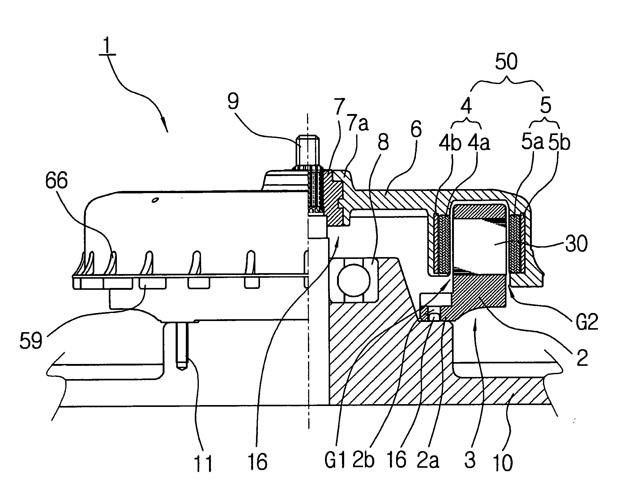
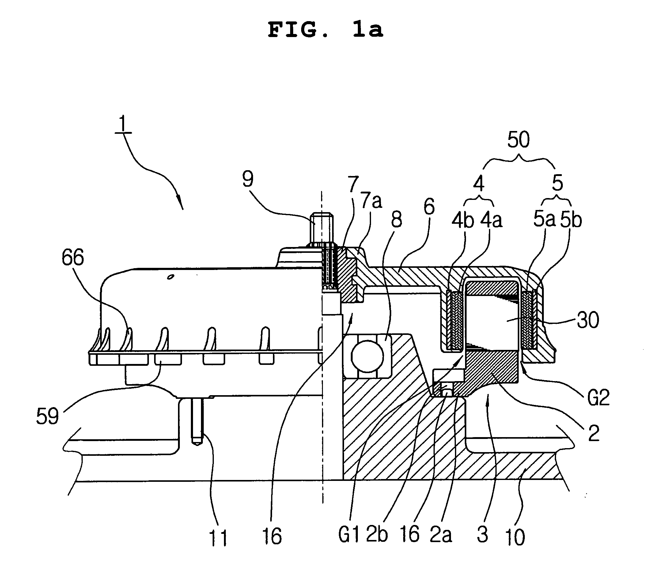
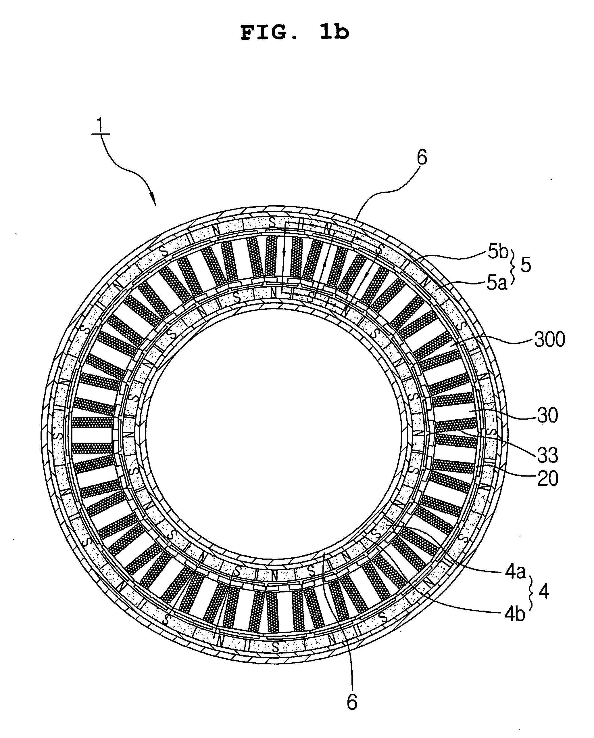
[0083]FIG. 1A is a partially cut-out cross-sectional view cut along the axial direction of a brushless direct-current (BLDC) motor of a radial core type having a structure of double rotors according to a first embodiment of the present invention, FIG. 1B is a cross-sectional view cut along the circumferential direction of the brushless direct-current (BLDC) motor of a radial core type having a structure of double rotors according to the first embodiment of the present invention, in order to illustrate a magnetic circuit, and FIG. 1C is a cross-sectional view of washing machine using the brushless direct-current (BLDC) motor according to the first embodiment of the present invention.

[0084]In the embodiment shown in FIGS. 1A and 1C, a brushless direct-current (BLDC) motor 1 of a radial core type having a structure of double rotors is installed in especially, the lower portion, i.e., housing 10 of an outer tub 112 in a washing machi...

second embodiment

II. Second Embodiment

[0186]Hereinbelow, the BLDC motor of the radial core type having a structure of double rotors according to a second embodiment of the present invention will be described.

[0187]FIG. 14 is an axial sectional view of a BLDC motor of a radial core type having a structure of double rotors according to a second embodiment of the present invention. FIG. 15A is a plan view of double rotors shown in FIG. 14. FIGS. 15B and 15C are a cross-sectional view and a rear view of the double rotors of FIG. 15A which is cut along a line X-X, respectively. FIG. 16A is a plan view of a stator shown in FIG. 14. FIGS. 16B and 16C are a cross-sectional view and a rear view of the stator of FIG. 16A which is cut along a line Y-Y.

[0188]Referring to FIG. 14, the BLDC motor 100 of the radial core type double rotor structure according to the second embodiment of the present invention includes a stator 330 in which a plurality of division cores 30 are integrally formed by an annular stator su...


PUM


Abstract

Provided are a radial core type brushless direct-current (BLDC) motor and a method of making the same, having an excellent assembly capability of division type stator cores in a double rotor structure BLDC motor. The BLDC motor includes a rotational shaft, an integrated double rotor including an inner rotor and an outer rotor, and a rotor supporter wherein a trench type space is formed between the inner rotor and the outer rotor, and an end extended from the inner rotor is connected with the outer circumferential surface of a bushing combined with the rotational shaft, and an integrated stator wherein one end of the stator is disposed in the trench type space and an extension axially extended from the other end of the integrated stator is fixed to the housing of the apparatus. In the integrated stator, U, V, W phase coil assemblies are formed of a number of core groups including a number of division type cores, wherein for each phase coil assembly, the division type core groups of the U, V, W phase coil assemblies are alternately disposed in an annular form in sequence of the phases, and the respective division type core groups are integrally formed into a single body in annular form by a stator support.

Description

BACKGROUND OF THE INVENTION[0001]1. Field of the Invention[0002]The present invention relates to a method of making an integrated stator, a radial core type brushless direct-current (BLDC) motor using the integrated stator, and a method of making the radial core type brushless direct-current (BLDC) motor, and more particularly, to a brushless direct-current (BLDC) motor having a radial core type double rotor structure which can greatly enhance productivity of assembling a stator in which coils are sequentially wound on a plurality of division type stator cores in a continuous winding method, and a plurality of interconnected stator core assemblies are automatically located and set using positioning grooves which are formed in a mold itself to then be injection-molded at an insert molding mode.[0003]2. Description of the Related Art[0004]BLDC motors are classified into a core type(or radial type), which has a generally cup-shaped(or cylindrical) structure, and a coreless type(or axia...

Claims


Application Information

Patent Timeline
IPC IPC(8): H02K1/00H02K1/28H02K1/12
CPCD06F37/304H02K1/14H02K1/27H02K1/30H02K3/28H02K3/524H02K21/12H02K7/14H02K9/06H02K15/095H02K15/12H02K16/02H02K5/22
Inventor KIM, BYOUNG KYULEE, JAE YEONGJEONG, KYU HYUKLEE, JONG HOON
Owner AMOTECH
Why Eureka
Try Eureka