Serpentine guard trace for reducing crosstalk of micro-strip line on printed circuit board

a technology of printed circuit board and serpentine guard trace, which is applied in the direction of cross-talk/noise/interference reduction, waveguide type devices, waveguides, etc., can solve the problems of difficult to remove the receiving-end crosstalk in a circuit, the strip line is more expensive in production than the micro-strip line, and the signal loss is serious, so as to and reduce the receiving-end crosstalk

Inactive Publication Date: 2007-10-11
POSTECH ACAD IND FOUND
View PDF2 Cites 24 Cited by
  • Summary
  • Abstract
  • Description
  • Claims
  • Application Information

AI Technical Summary

Benefits of technology

[0016]In addition, the second section length increases by reducing the serpentine guard trace width to be less than the first and second transmission line widths.
[0017]Accordingly, the channel structure according to the present invention can effectively reduce the receiving-end crosstalk by changing the conventional linear structure of the guard trace for reducing the receiving-end crosstalk with the serpentine structure. In addition, the receiving-end crosstalk is more easily reduced by disposing the serpentine guard trace between the two signal lines separated by a given distance in the high speed system in which the area of the printed circuit board is limited.

Problems solved by technology

The far-end crosstalk is a phenomenon due to an electromagnetic interference and causes serious signal loss when transmitting a high speed signal.
Accordingly, it is difficult to remove the receiving-end crosstalk in a circuit.
However, the strip line is more expensive in production than the micro-strip line.
As shown in FIG. 7, when the conventional guard trace is used, the receiving-end crosstalk is partially reduced, and, however, the system performance cannot be remarkably improved.

Method used


Image

  • Serpentine guard trace for reducing crosstalk of micro-strip line on printed circuit board
  • Serpentine guard trace for reducing crosstalk of micro-strip line on printed circuit board
  • Serpentine guard trace for reducing crosstalk of micro-strip line on printed circuit board

Examples


Embodiment Construction

[0030]The attached drawings for illustrating exemplary embodiments of the present invention are referred to in order to gain a sufficient understanding of the present invention, the merits thereof, and the objectives accomplished by the implementation of the present invention.

[0031]Hereinafter, the present invention will be described in detail by explaining exemplary embodiments of the invention with reference to the attached drawings. Like reference numerals in the drawings denote like elements.

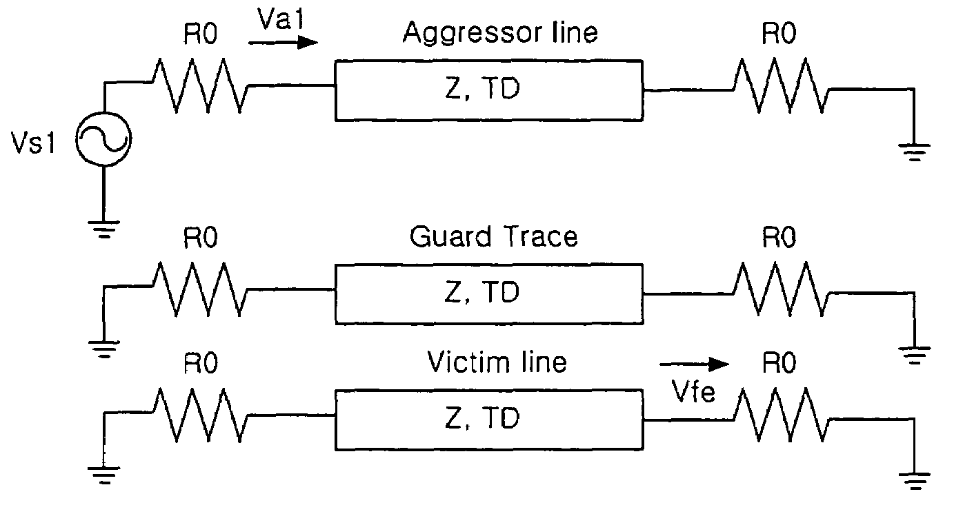
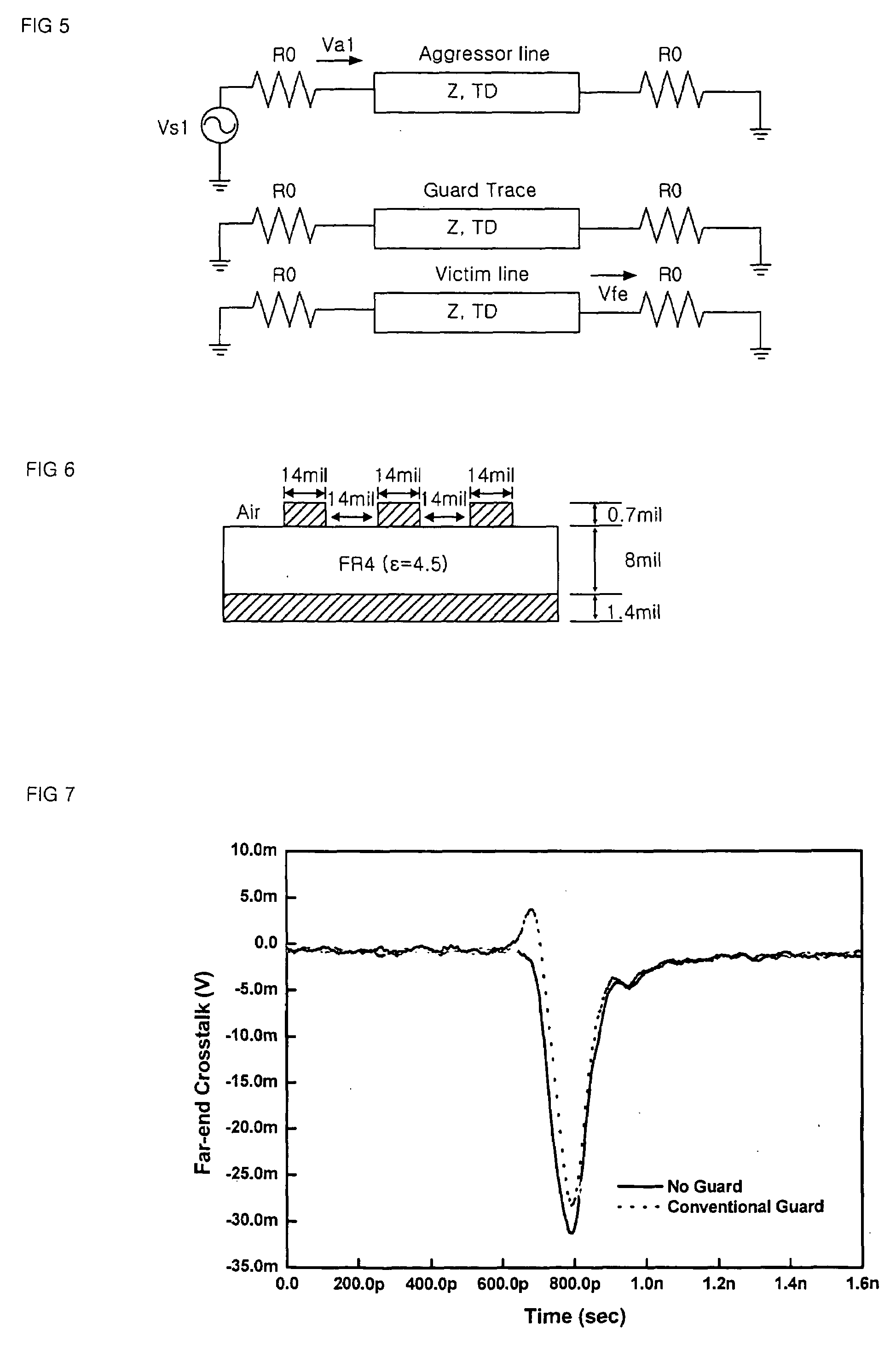
[0032]FIG. 8 is a block diagram of a channel including a serpentine guard trace according to the present invention. Referring to FIG. 8, a serpentine guard trace 730 is disposed between two transmission lines 710 and 720. The serpentine guard trace 730 is longer than the conventional linear guard trace of FIG. 5. To efficiently increase a length of L2, a guard trace width W2 is reduced to be less than a transmission line width W1. In addition, the characteristic impedance increases by reduci...


PUM


Abstract

A serpentine guard trace for reducing far-end crosstalk of a micro strip transmission line is provided. The serpentine guard trace reduces receiving-end crosstalk caused by an electromagnetic interference of a signal of a nearby transmission line when transmitting a high speed signal through a micro strip transmission line on a printed circuit board. The serpentine guard trace is located between two nearby transmission lines and has a line width narrower than that of transmission lines for an effective serpentine structure. A characteristic impedance of the serpentine guard trace increases due to the narrow line width. Termination resistors having impedance which is the same as the characteristic impedance of the serpentine guard trace are located on both ends of the guard trace to minimize a reflection wave generated in the serpentine guard trace. The receiving-end crosstalk can be effectively reduced by using the serpentine guard trace instead of a linear guard trace. Accordingly, the serpentine guard trace can be effectively used when a high speed signal is transmitted on a printed circuit board.

Description

BACKGROUND OF THE INVENTION[0001]1. Field of the Invention[0002]The present invention relates to a transmission line, and more particularly, to a channel structure including a serpentine guard trace for reducing receiving-end crosstalk caused by electromagnetic interference of a signal of a nearby transmission line when transmitting a high speed signal through a transmission line on a printed circuit board.[0003]2. Description of the Related Art[0004]Far-end crosstalk refers to an interference between a signal transmitted through one transmission line and a signal transmitted through a nearby transmission line when transmitting the signal using a plurality pairs of transmission lines. The far-end crosstalk is a phenomenon due to an electromagnetic interference and causes serious signal loss when transmitting a high speed signal.[0005]FIG. 1 is a schematic diagram illustrating the far-end crosstalk occurring in the other transmission line 120 when a signal is applied to one of two ne...

Claims


Application Information

Patent Timeline
Patent Type & Authority Applications(United States)
IPC IPC(8): H03H3/08
CPCH01P3/081H05K1/0219H05K2201/09727H05K2201/09263H05K2201/09236H05K1/11H05K1/16
Inventor LEE, HYUN BAEPARK, HONG JUNE
Owner POSTECH ACAD IND FOUND
Why Eureka
Try Eureka