Antenna device and wireless communication apparatus using same

a wireless communication apparatus and antenna device technology, applied in the field of antenna devices, can solve the problems of complicated configuration, occupying space in the antenna device area of the antenna circuit, and affecting the operation so as to improve the degree of freedom of arrangement (layout) of the antenna device, save space for the antenna device, and miniaturize the wireless communication apparatus

Inactive Publication Date: 2007-10-11
HITACHI METALS LTD
View PDF5 Cites 27 Cited by
  • Summary
  • Abstract
  • Description
  • Claims
  • Application Information

AI Technical Summary

Benefits of technology

[0056] Owing to this, it is made possible to save space for the antenna device embedded in the wireless communication apparatus and to increase a degree of freedom of arrangement (layout) of the antenna device in the wireless communication apparatus and to achieve the miniaturization of the wireless communication apparatus.
[0057] With the above configuration, it is made possible to realize a small-sized antenna device which can operate in a wide band (in a plurality of transmitting and receiving frequency bands) and obtain excellent gain in every band of transmitting and receiving frequencies and maintain non-directivity of vertically polarized waves.
[0058] Therefore, when the

Problems solved by technology

However, such a conventional antenna device has problems.
Furthermore, in the conventional antenna device, power is fed to every antenna corresponding to each transmitting and receiving frequency band and, therefore, antenna switches are required, which causes the antenna circuit on the circuit to occupy space in the antenna device area.
However, the antenna switches used in the conventional antenna device to allot signals have complicated configurations and large insertion loss occurs in the UMTS band of high frequencies in particular.
Moreover, the above conventional antenna device presents another problem in that signals in all the DCS, PCS, GMC, and UMTS bands are handled in a shared manner using a single power feeding port, a deviation occurs in diffusion of radio waves, causing non-uniformity of directivity of vertically polarized waves in the antenna corresponding to each of the transmitting and receiving frequency bands.
Moreover, when these antennas are applied to a wireless communication apparatus such as a mobile phone, antenna switches to switch the transmitting

Method used


Image

  • Antenna device and wireless communication apparatus using same
  • Antenna device and wireless communication apparatus using same
  • Antenna device and wireless communication apparatus using same

Examples


first embodiment

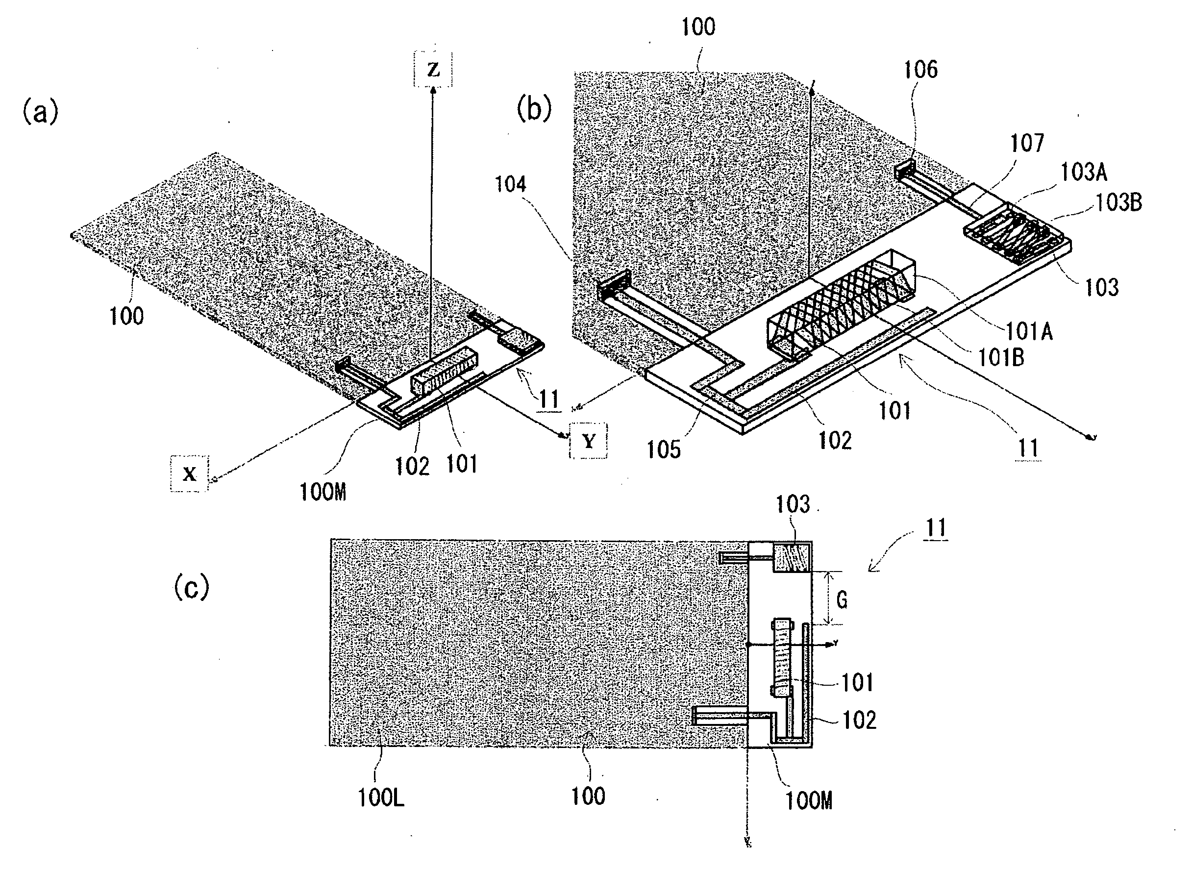
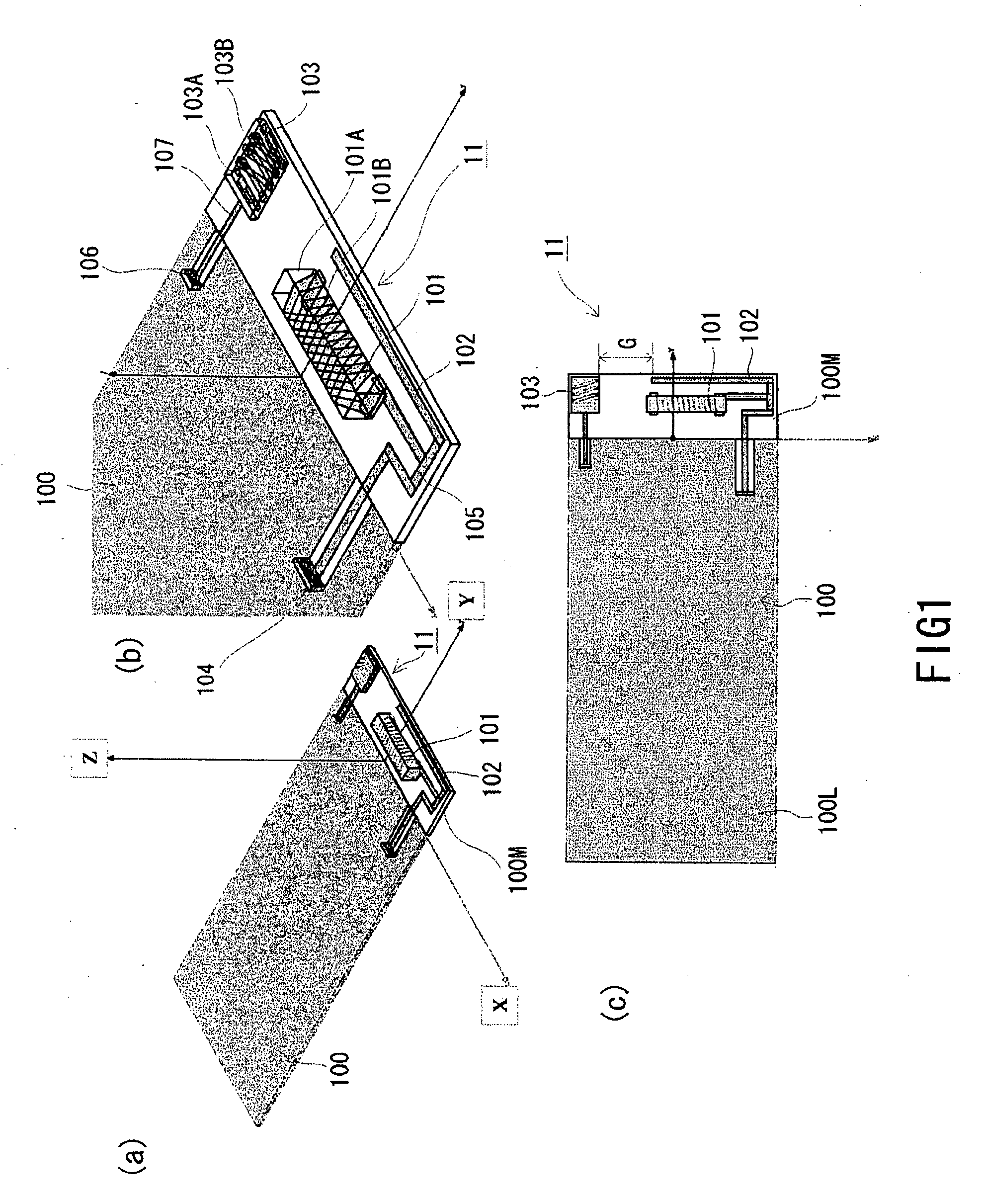
[0090] As shown in FIGS. 1(a), 1(b), and 1(c), the antenna device 11 of the first embodiment includes a substrate 100, the first antenna 101 and second antenna 102, and third antenna 103, all being mounted on a substrate 100.

[0091] Each of these first, second, and third antennas operates in transmitting and receiving frequency bands each being different from one another. More specifically, the first antenna 101 operates in a GSM band (900 MHz band), the second antenna 102 in a DCS band (1700 MHz band) and a PCS band (1800 MHz band), and the third antenna 103 in an UMTS band (2200 MHz band), thereby achieving the quad-band type antenna device 11.

[0092] Thus, the first antenna 101 operates in the transmitting and receiving frequency band of frequencies being lower than those in the DCS band and the PCS band applied to the second antenna and than the UMTS band applied to the third antenna 103. The second antenna 102 operates in two transmitting and receiving bands of the DCS band and ...

second embodiment

[0187] In the antenna device 21 of the first example of the second embodiment, as shown in FIGS. 16(a) and 16(b), the first antenna 101 is mounted on the main face (surface) of the substrate 100 and the second antenna 102 is mounted on the rear face 100R of the substrate 100. The second antenna 102 is connected to a line 105 for the first antenna 101 formed on the main surface 100P on a power feeding side via a through hole electrode 116.

[0188] Operations of the antenna device 21 are the same as those of the antenna devices of the first and second examples of the first embodiment in that signals in the GSM band being a transmitting and receiving frequency band for the first antenna 101 and signals in the DCS and PCS bands being a transmitting and receiving frequency band for the second antenna 102 are processed by the same transmitting and receiving circuit and in that a pattern antenna making up the second antenna 102 is connected to the line 105 which connects a chip antenna makin...

third embodiment

[0207] In the antenna device 30 of the third embodiment, as shown in FIGS. 19(a) and 19(b), the second antenna 102 is configured as a chip antenna as for the first antenna 101.

[0208] That is, the second antenna 102 consists of a base body 102A made up of a dielectric and a conductor 102B wound around a surface of the base body 102A. However, the second antenna 102 is constructed so that its length is the same as that of the first antenna 101 and its width and height are smaller than that of the first antenna 101.

[0209] Also, the second antenna 102 is constructed so that an interval between the conductors 102B is larger than that applied to the first antenna 101 and so that the conductors 102B is wound around the base body 102A with a smaller number of windings compared with the number of windings used for the first antenna 101.

[0210] This is because the transmitting and receiving frequencies to be used by the second antenna 102 are higher than those used by the first antenna 101. ...


PUM


Abstract

An antenna device is provided which is capable of operating in a wider band of frequencies (in a plurality of transmitting and receiving frequency bands), achieving an excellent gain, maintaining non-directivity of vertically polarized waves in each of the transmitting and receiving frequency bands, and saving space. The antenna device includes the first antenna 101 being a chip-type antenna operating in a GSM band, second antenna 102 being a pattern antenna operating in DCS and PCS bands, third antenna 103 being a layer-stacked antenna operating in an UMTS band, all being mounted on a substrate 100. The second antenna 102 is connected to a line 105 extending from a power feeding port 104 connected to the first antenna 101. A gap is interposed between the second antenna 102 and third antenna 103 wherein the second antenna 102 is capacitively coupled to the third antenna 103 on the substrate 100 with no antenna switch being provided.

Description

BACKGROUND OF THE INVENTION [0001] 1. Field of the Invention [0002] The present invention relates to an antenna device and more particularly to the antenna device that can operate in a plurality of frequency bands and a wireless communication device using the antenna device. [0003] 2. Description of the Related Art [0004] In recent years, a wireless communication apparatus such as a mobile phone or a like has become widespread and various bands of frequencies are used in communications. [0005] In a recently-available mobile phone called a dual-band, triple-band, or quad-band type mobile phone in particular, one mobile phone is made to operate in a plurality of transmitting and receiving frequency bands. [0006] In such a circumstance, hurried development of an antenna device making up antenna circuits embedded in a mobile phone or a like being capable of operating in the plurality of transmitting and receiving frequency bands described above is needed. [0007] It is thus necessary tha...

Claims


Application Information

Patent Timeline
IPC IPC(8): H01Q1/38H01Q5/00H01Q5/10H01Q5/371H01Q5/378H01Q11/08H01Q21/30H04B1/38H04B1/3822
CPCH01Q1/243H01Q1/362H01Q5/371H01Q21/28H01Q21/30H01Q5/00H01Q1/38
Inventor AOYAMA, HIROYUKIKAZAMA, KAZUO
Owner HITACHI METALS LTD
Why Eureka
Try Eureka