Lithium niobate coated optical fiber apparatus and method

Inactive Publication Date: 2007-10-11
FANASYS
View PDF4 Cites 18 Cited by
  • Summary
  • Abstract
  • Description
  • Claims
  • Application Information

AI Technical Summary

Benefits of technology

[0014] It is a further object and advantage of the present invention to provide a sensor system with lower coupling losses.
[0015] It is an additional object and advantage of the present invention to provide a sensor system with lower interference.
[0016] In accordance with the foregoing objects and advantages, the present invention provides an electro-optic modulator/sensor having a thin lithium niobate (LiNbO3) film at the core/cladding interface of an optical fiber. The optical fiber is drawn from a fiber preform that is processed with a sol-gel formulation of lithium niobate so as to have a thin film sol-gel layer of lithium niobate between the core and cladding regions of an optical fiber preform. The fiber includes a central core and a cladding layer disposed about the core wherein the central core and the cladding layer are each made from glass materials having different indices of refraction. A thin film of lithium niobate is disposed between the core/cladding interface wherein the lithium niobate is sensitive to changes in stress and strain to cause light to modulate through the fiber.
[0017] The lithium niobate layer has an index of refraction that is caused to change upon imposition of stress or strain induced through physical means or by creation of an electric field. In one version, the fiber includes in cross section a polished flattened cladding region wherein the fiber assumes a substantially D-shaped geometry. This geometry permits the attachment of electrodes onto the flattened cladding region wherein an electric field can be created across the electrodes and the lithium niobate layer. The sensitivity of the

Problems solved by technology

The intention to maximize modulation of a selected light beam property or properties, however, is diametrically opposite to the desired objective of minimizing differences between input and output light in data transmission.
Because of cost and relative development, practical circuits at present consist of mixed electronic and photonic components.
Circuits consisting entirely of photonic transmission, sensing, processing and actuation are not practical or economical at this time.
While the technology for such a system exists, associated costs and complexity remain high.
With the above background provided, it is well known that splicing of very different core sized fiber segments introduces excessive l

Method used


Image

  • Lithium niobate coated optical fiber apparatus and method
  • Lithium niobate coated optical fiber apparatus and method
  • Lithium niobate coated optical fiber apparatus and method

Examples


Embodiment Construction

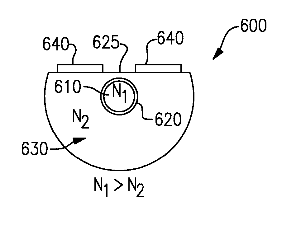
[0035] Referring now to the drawings, wherein like reference numerals refer to like parts throughout, there is seen in FIG. 6 a drawn cylindrical optical fiber 500 according to an embodiment of the present invention. Fiber 500 includes a glass central core 510 having an index of refraction n1, a glass cladding 530 having an index of refraction n2, where n1 is greater than n2, and a uniform, thin film layer of lithium niobate (LiNbO3) 520 disposed between the core 510 and cladding 530. Thin film layer 520 is a sol-gel material formed from lithium niobate (LiNbO3), a crystal with excellent electro-optic and acousto-optic properties. The index of refraction (n3) of thin film LiNbO3 changes slightly and in proportion with the application of an electric field (electro-optic effect) or the application of stress (piezoelectric effect).

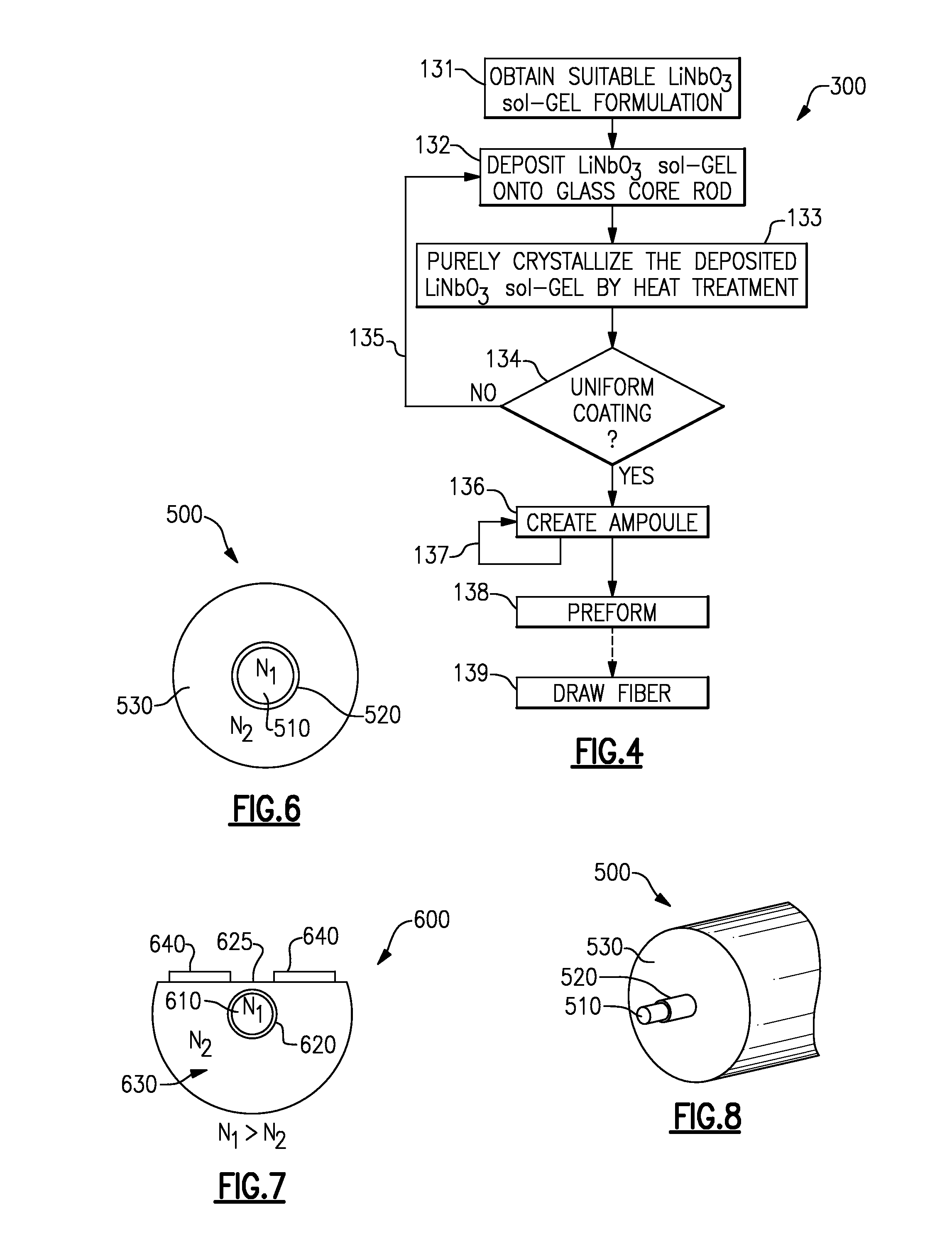
[0036] There is seen in FIG. 4, a process 300 for making an optical fiber preform that is used to form a lithium niobate optical fiber, such as that shown i...


PUM


Abstract

An optical fiber sensor having a central core, a cladding layer disposed about the central core, and a thin film of lithium niobate positioned between the core and the cladding layer. Each of the cladding layer and the central core are made from glass materials having different indices of refraction. The refractive index of the lithium niobate film changes when stress is applied to the optical fiber sensor. Accordingly, stress may be detected and measured by detecting and measuring the modulation of light passing through the optical fiber sensor while the stress is occurring.

Description

CROSS-REFERENCE TO RELATED APPLICATIONS [0001] This application claims priority to U.S. Provisional Patent Application Ser. No. U.S. 60 / 728,959, filed on Oct. 21, 2006.BACKGROUND OF THE INVENTION [0002] 1. Field of the Invention [0003] The present invention relates to optical fibers and, more particularly, to a single-mode optical fiber having an inter-core coated film of lithium-niobate fiber acting as a modulator / sensor. [0004] 2. Description of the Related Art [0005] As shown in FIG. 1, an ordinary optical or plain fiber 10 is a wave-guide through which light is propagated by continuous total internal reflection within a glass central core 14 of the fiber. The glass surrounding the central core 14 is known as the cladding 18. Both core 14 and cladding 18 are dielectric materials. Because the index of refraction (n1) of core 14 is made to be higher than that of the surrounding cladding (n2), light waves remain trapped within core 14 during transmission. Depending on the wave modes...

Claims


Application Information

Patent Timeline
IPC IPC(8): G02B6/02
CPCG01L1/242G01M11/088G02B6/03622G01D5/3538G02F1/035G02F2201/02G02F2202/20G02F1/0134
Inventor JAMISON, TRACERKELLER, DOUGLAS V.KORNREICH, PHILIPPFLATTERY, JAMES
Owner FANASYS
Why Eureka
Try Eureka