Reference Devices for Placement in Heart Structures for Visualization During Heart Valve Procedures

Inactive Publication Date: 2007-10-11
MEDTRONIC VASCULAR INC
View PDF9 Cites 196 Cited by
  • Summary
  • Abstract
  • Description
  • Claims
  • Application Information

AI Technical Summary

Benefits of technology

[0020]The visualization reference devices of the current invention can be made completely or in part from material having a desired degree of visibility when using non-direct visualization technology. Alternately, the devices can be completely or partially coated with materials that are visible when using non-direct visualization, or they can include coils having electro magnetic or electro potential properties. When using a visualization reference device, alone or in a combination with other devices, a clinician can take multiple images of a heart in dyastole and systole. These images can be taken from different angles or the same angle and they can be superimposed upon each other to provide a clinician with a good image of the heart structure and the location of a valve annulus.
[0021]Anot

Problems solved by technology

Heart valves, such as the mitral and tricuspid valves, are sometimes damaged by diseases or by aging, which can cause problems with the proper function of the valve.
This results in reduced ejection volume from the left ventricle, causing the left ventricle to compensate with a larger stroke volume.
The increased workload eventually results in dilation and hypertrophy of the left ventricle, further enlarging and distorting the shape of the mitral valve.
If left untreated, the condition may result in cardiac insufficiency, ventricular failure, and death.
Non-direct visualization of the valve annulus is challenging.
Cardiac tissues do not appear under fluoroscopy, making it very difficult to accurately align the valve repair device prior to its implantation.
However, when treating the mitral valve, repeated injections of contrast dye are not practical because of rapid wash-out in the high-flow area being treated.
Additionally, to make the high-volume contrast injections, the annuloplasty catheter system would require more lumens, larger lumens, or an additional catheter, none of which is desirable during catheterization procedures.
Furthermore, multiple high-volume contrast i

Method used


Image

  • Reference Devices for Placement in Heart Structures for Visualization During Heart Valve Procedures
  • Reference Devices for Placement in Heart Structures for Visualization During Heart Valve Procedures
  • Reference Devices for Placement in Heart Structures for Visualization During Heart Valve Procedures

Examples


Embodiment Construction

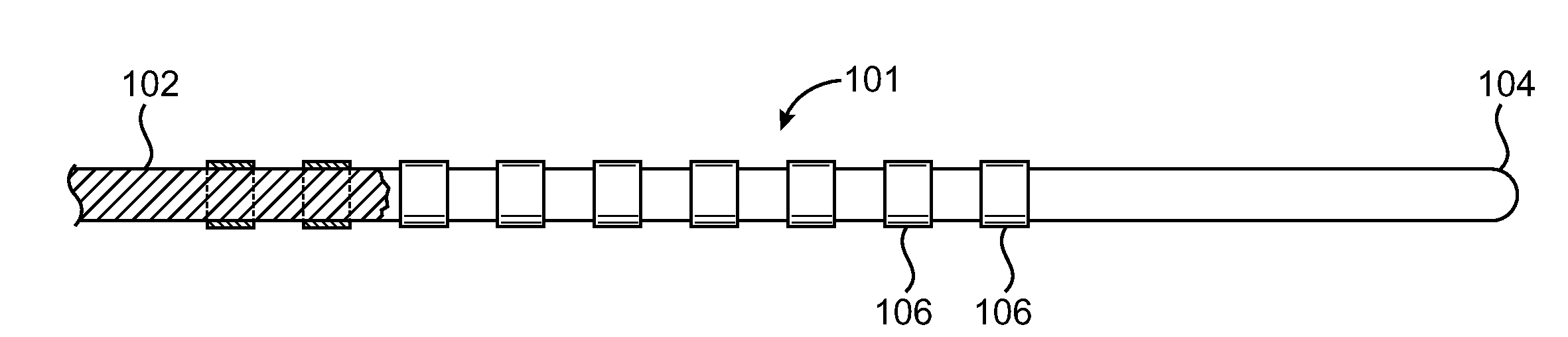
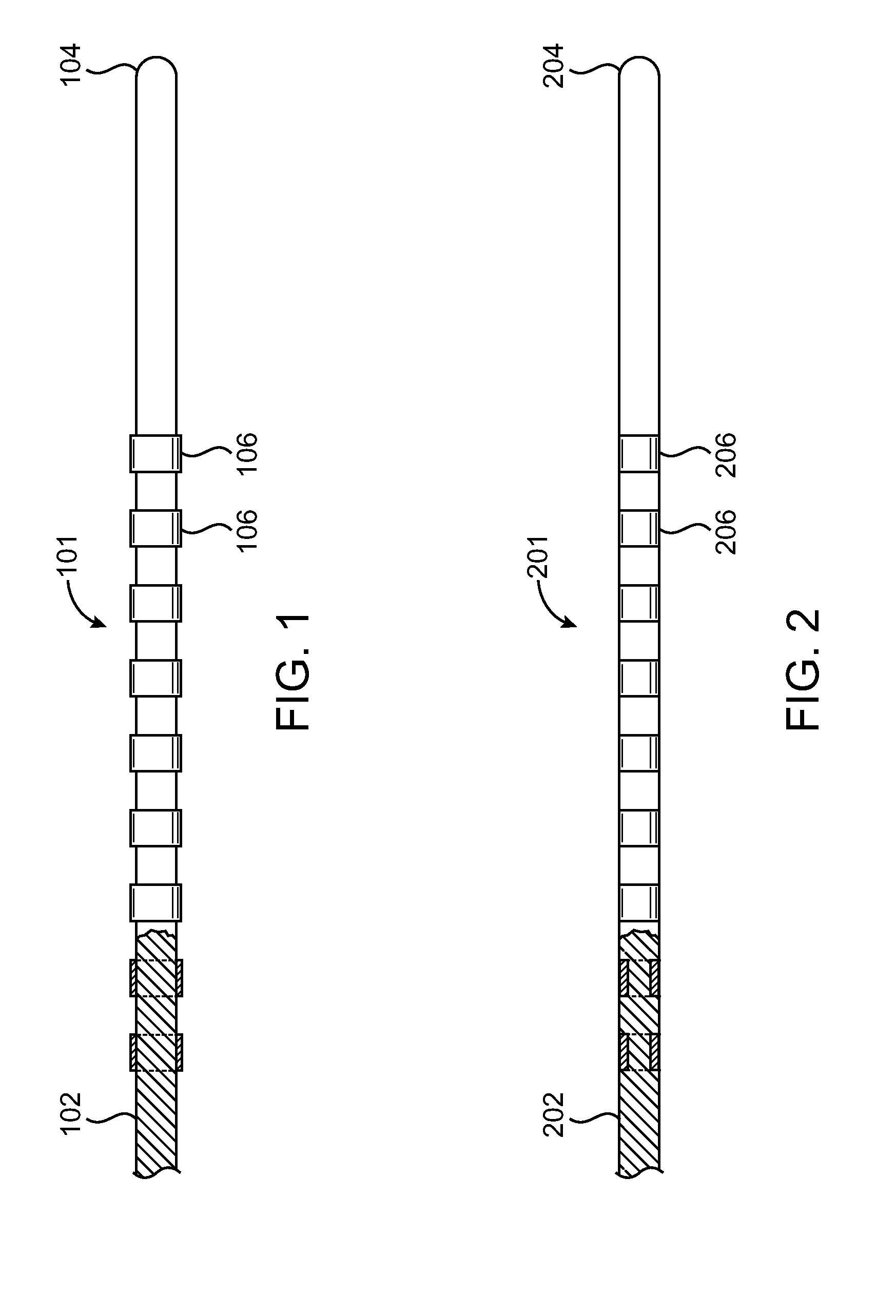
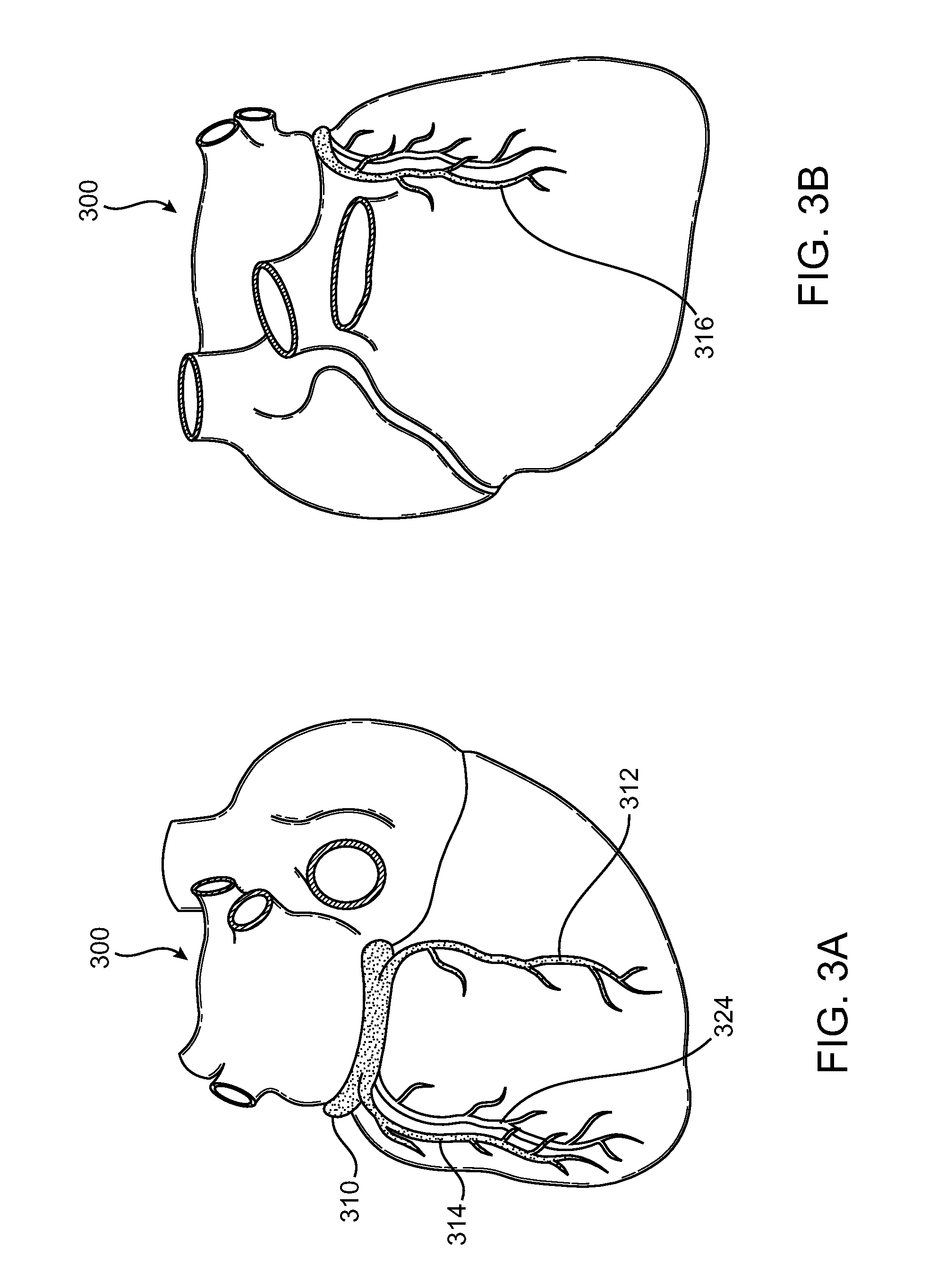
[0032]The invention will be describe by reference to the drawing figures, where like numbers refer to like parts. One aspect of the present invention is to provide visualization reference devices that have non-direct visualizable properties, for aiding in placement of an implantable valve repair device in abutment with a heart valve annulus. Documents disclosing devices for valve repair are U.S. Patent Application having the Publication No. 2007 / 005,1377, entitled “Cardiac Valve Annulus Reduction System,” by Douk et al. and U.S. Patent Application having the Publication No. 2007 / 002,7533, entitled “Cardiac Valve Annulus Restraining Device,” by Douk, the contents of these applications is incorporated herein by reference thereto.

[0033]The visualization reference devices are designed to be temporarily positioned using intravascular catheterization techniques. Alternatively, surgical or minimally invasive, i.e. endoscopic techniques may be used to place the devices.

[0034]The reference d...


PUM


Abstract

Visualization reference devices to aid in non-direct visualization of heart structure. The devices are positionable in the heat structure and visible with a desired imaging modality. The devices being elastically transformable between delivery configurations and deployment configurations. The devices being used to assist a clinician in mapping the heart structure while implanting therapeutic devices therein. An example would be using the devices disclosed herein to map the size, location, orientation and displacement of a mitral valve annulus for catheter based implantation of a valve repair device.

Description

CROSS-REFERENCE TO RELATED APPLICATION[0001]The present application claims priority to U.S. Provisional Application No. 60 / 743,687, filed Mar. 23, 2006 and titled “Reference Devices for Placement in Heart Structures for Visualization During Heart Valve Procedures”, the entire contents of which is incorporated herein by reference in its entirety.TECHNICAL FIELD[0002]This invention relates generally to medical devices and particularly to a device, system, and method for aiding implantation of a heart valve repair device.BACKGROUND OF THE INVENTION[0003]Heart valves, such as the mitral and tricuspid valves, are sometimes damaged by diseases or by aging, which can cause problems with the proper function of the valve. The mitral and tricuspid valves consist of leaflets attached to a fibrous ring or annulus. In a healthy heart, the mitral valve leaflets overlap during contraction of the left ventricle, or systole, and prevent blood from flowing back into the left atrium. However, due to v...

Claims


Application Information

Patent Timeline
IPC IPC(8): A61B5/05
CPCA61B5/055A61B5/103A61B6/12A61B8/0833A61B19/54A61B5/6869A61B2019/463A61B2019/5425A61B5/6855A61B5/6858A61B2017/00243A61B2090/063A61B90/39A61B2090/3925
Inventor HUYNH, RANYRAFIEE, NASSERHILL, ALEXDOUK, NAREAK
Owner MEDTRONIC VASCULAR INC
Why Eureka
Try Eureka