
Therapeutic treatment apparatus

a technology of treatment apparatus and treatment device, which is applied in the field of therapeutic treatment device, can solve the problems of ineffectiveness of laser for the removal of birth and age marks, inability to effectively treat the second type of skin disorder, and complicated lasers, and achieve the effect of optimal penetration depth

Inactive Publication Date: 2007-10-11
CYDEN
View PDF5 Cites 11 Cited by
  • Summary
  • Abstract
  • Description
  • Claims
  • Application Information

AI Technical Summary

Benefits of technology

[0009] Accordingly, a wide band electromagnetic radiation source covering the near UV and the visible region of the spectrum, and optionally the near infra-red, is desirable for treatment of external skin and vascular disorders. The range of wavelengths of the light source should be sufficient to optimize treatment for any of a number of applications. Such a therapeutic radiation apparatus should also be capable of providing an optimal wavelength range within the overall range for the specific disorder being treated. The intensity of the light should be sufficient to cause the required internal and / or external thermal effect by raising the temperature in or around the treatment area to the required temperature, but without causing pain or skin problems. Also, the pulse width should be variable over a wide enough range so as to achieve optimal penetration depth for each application.

Problems solved by technology

The effectiveness of lasers for applications such as tattoo removal and removal of birth and age marks is diminished because lasers are monochromatic.
A laser of a given wavelength may be effectively used to treat a first type of skin pigmentation disorder, but, if the specific wavelength of the laser is not absorbed efficiently by skin having a second type of disorder, it will be ineffective for the second type of skin disorder.
Also lasers are usually complicated, expensive to manufacture, large in comparison to the amount of power delivered, unreliable and difficult to maintain.
As this takes place in the entire area treated and as it spreads out with the bloodstream and furthermore lasts for a period of time, this effect is undesirable.

Method used


Image

  • Therapeutic treatment apparatus
  • Therapeutic treatment apparatus
  • Therapeutic treatment apparatus

Examples


Embodiment Construction

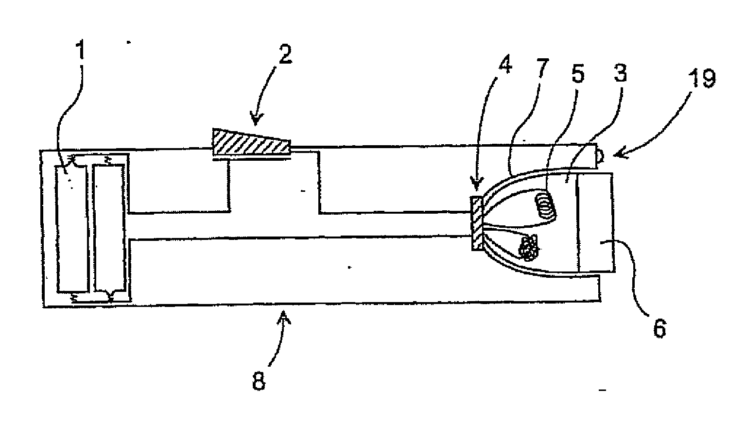
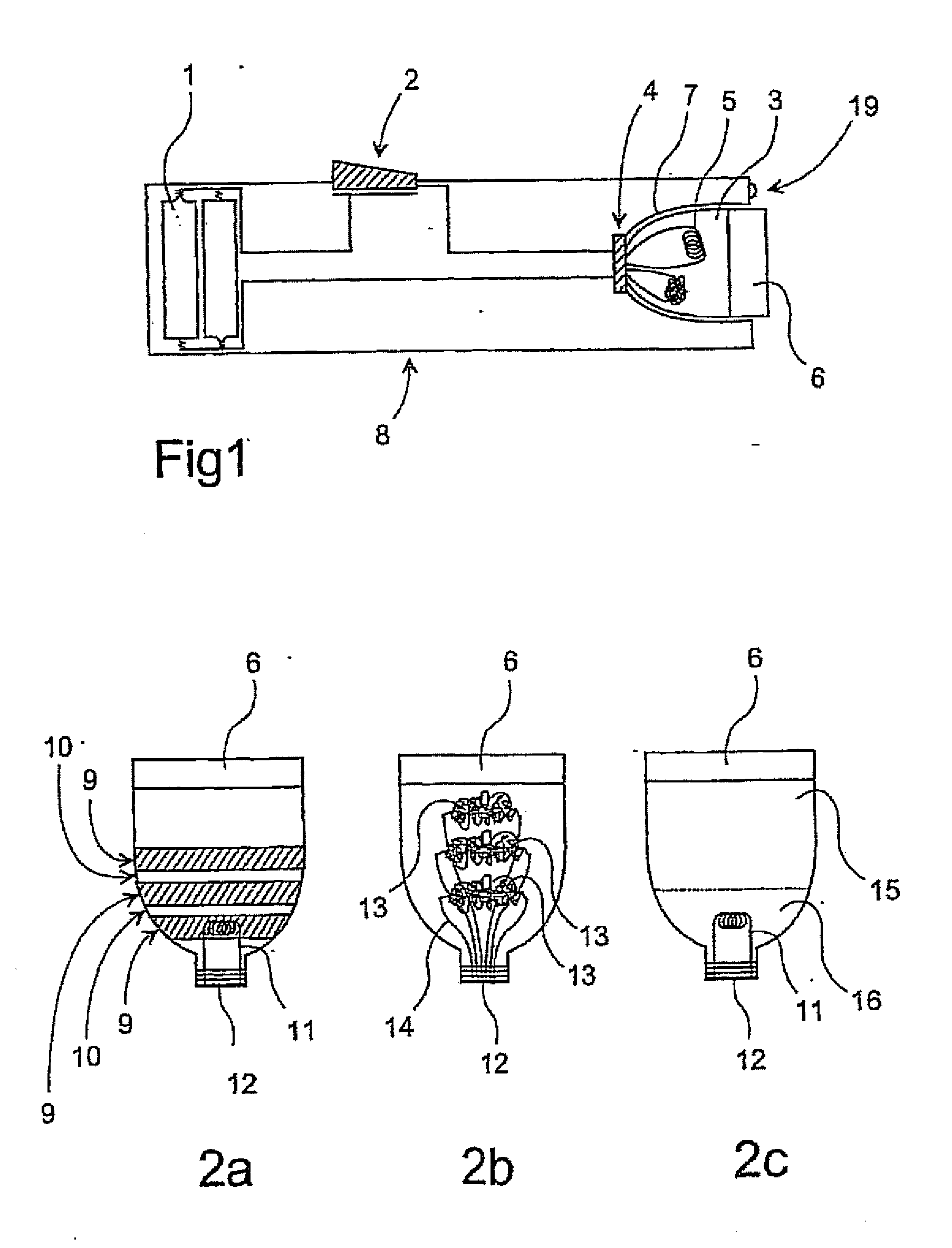
[0057] In FIG. 1 is illustrated self-contained apparatus according to the invention, which can in some aspects be compared to a common flash light. Batteries 1 represent the electrical energy source and a trigger switch 2 is mounted on a conductor connecting the batteries to a disposable incoherent light source 3. The disposable light source is in this embodiment a disposable flash bulb, which is mounted in a socket 4.

[0058] Before each use, a new suitable flash bulb, that is to say an incoherent light source 3 is mounted in the socket 4. When the switch makes the electrical contact, current passes to the light source 3, whereby ignitable material 5 is ignited and emits light. In this embodiment of the invention a light source having an optical block 6 mounted in front of the light source is illustrated. Part of the emitted light from the ignition of the material 5 passes straight through the prism or optical block 6 and into the treatment area. The rest of the light is bounced off...


PUM


Abstract

The apparatus for non-invasive treatment of skin disorders or removal of unwanted hair comprises a reflector unit having therein at least one light source for emitting incoherent light, the reflector unit and the light source being replaceable after activation thereof and disposable after such replacement. The apparatus includes an energy source for providing an electrical current to the light source or light sources, an on / off switch for selectively triggering supply of the electrical current to the light source or light sources and preventing said current supply; and a controller for controlling at least one of the intensity, the pulse length and the sequence of each light source, at least one of the light sources being adapted to emit a series of light pulses.

Description

CROSS-REFERENCE TO RELATED APPLICATIONS [0001] This application is a Continuation-In-Part of U.S. patent application Ser. No. 10 / 473,672, filed Oct. 30, 2003, which is a National Phase of International Application No. PCT / DK01 / 00799, filed Nov. 30, 2001, which claims priority to Denmark Patent Application Serial No. PA 2001-00550, filed Mar. 30, 2001; and also of U.S. patent application Ser. No. 10 / 520,515, filed Jan. 7, 2005, which is a National Phase of International Application No. PCT / DK03 / 00349, filed May 27, 2003, which claims priority to Denmark Patent Application Serial No. PA 2002-01075, filed Jul. 8, 2002, all of which are incorporated herein by reference.TECHNICAL FIELD [0002] The present invention concerns therapeutic treatment apparatus for non-invasive treatment of skin disorders such as discoloration, acne, wrinkles, visible blood vessels, cellulite and stretch marks, or for removal of unwanted hair, softening of scar tissue and the like. BACKGROUND OF THE INVENTION [...

Claims


Application Information

Patent Timeline
IPC IPC(8): A61N5/06A61B18/00A61B18/18A61B18/20
CPCA61B18/203A61B2018/00005A61B2018/00452A61B2018/00458A61B2018/00476A61B2018/1807
Inventor SIMONSEN, JANBJERRING, PETER
Owner CYDEN
Learn More