
High-temperature membrane for CO2 and/or H2S separation

a high-temperature membrane and co2 technology, applied in the field of co2and h2s separation membranes, can solve the problems of not being suitable for large-scale power plants, not being cost-effective, other technologies are not yet mature, etc., and achieve the effect of increasing hydrogen production, high diffusion flux, and ensuring the separation of co2

Inactive Publication Date: 2007-10-18
GAS TECH INST
View PDF14 Cites 38 Cited by
  • Summary
  • Abstract
  • Description
  • Claims
  • Application Information

AI Technical Summary

Benefits of technology

[0009] It is another object of this invention to provide a method and apparatus for selective removal of CO2 from CO2-containing fluids which overcomes some of the disadvantages of known CO2 removal techniques discussed herein above.
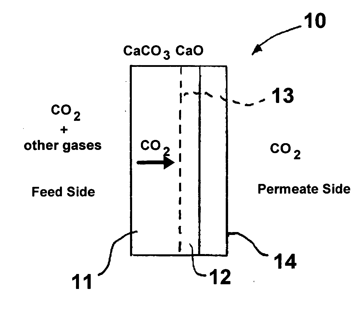
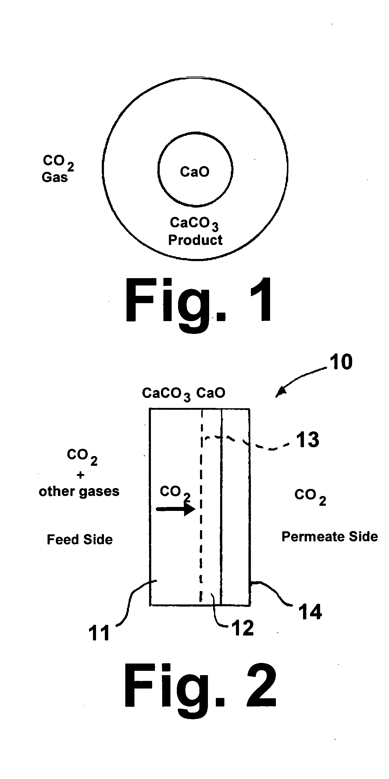
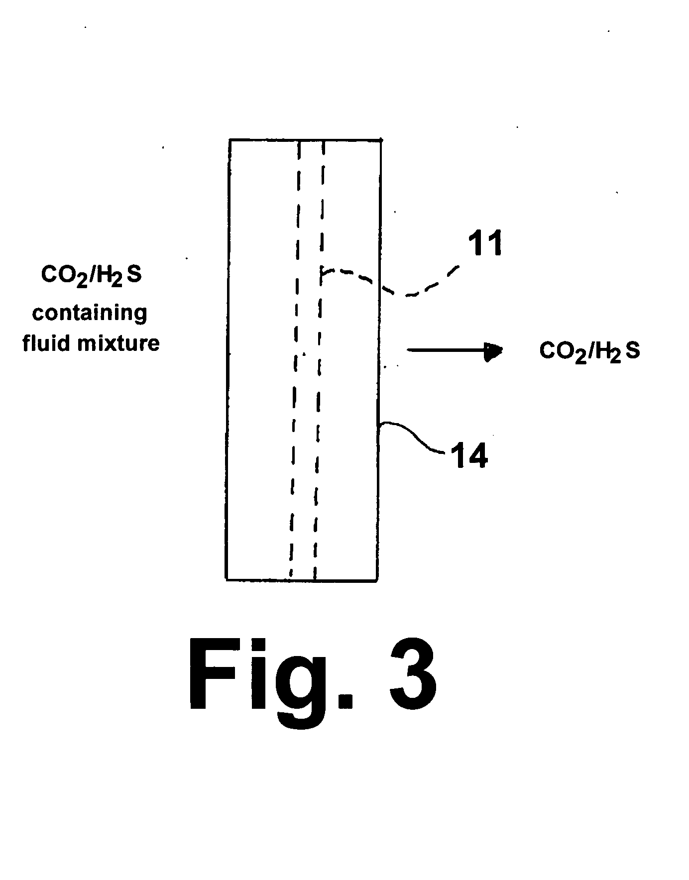
[0012] The concept of this invention is based upon the fact that the dense carbonate membranes allow only CO2 in the form of carbonate ions and / or H2S in the form of sulfide ions to diffuse through and exclude all other gas species present in the gaseous mixture, including hydrogen. Thus, the method of this invention can achieve 100% selectivity for CO2 and / or H2S on the permeate side of the membranes. The membranes can operate at higher temperatures (greater than 200° C.) than conventional membranes to enable higher diffusion flux for the carbonate (CO32−) ions. The high-temperature membranes of this invention are suitable for use in applications for CO2 separation from fuel / flue gas or synthesis gas without the need of gas cooling. They can be used as a membrane reactor with the water gas shift reaction to increase hydrogen production by removing the equilibrium limitation. The catalysts of the water gas shift reaction may be eliminated if the membrane reactor is operated at sufficiently high temperatures (greater than about 500° C.). More importantly, hydrogen is produced at the feed pressure of the synthesis gas as opposed to the low pressure hydrogen generated from other hydrogen-selective membranes.

Problems solved by technology

However, it is not considered to be cost-effective and it is not suitable for use in large-scale power plants.
The other technologies are not yet mature or cannot be applied economically at the scale required for power plants.
However, the chemical interaction may make the reaction irreversible and would result in lower permeation rates.

Method used


Image

  • High-temperature membrane for CO2 and/or H2S separation
  • High-temperature membrane for CO2 and/or H2S separation
  • High-temperature membrane for CO2 and/or H2S separation

Examples


example

[0031] In this example, a nonporous CaCO3 membrane was produced using CaCl2.2H2O powder obtained from Alfa-Aesar, Ward Hill, Mass., Na2CO3 powder obtained from Aldrich Chemical Company, Milwaukee, Wis., and a porous alfa-alumina support tube having a nominal pore size of 50 nm, an inside diameter of 3.5 mm, an outside diameter of 5.5 mm and a length of 2 inches obtained from Media and Process Technology, Inc., Pittsburgh, Pa. The support tube was closed at one end using a silicone stopper and filled with 0.5M CaCl2 solution. The filled tube was immediately dipped into another solution containing 0.5M Na2CO3. Care was taken to avoid mixing of the two solutions except at an interface within the support tube wall, where calcium and carbonate ions react to form CaCO3 crystals. After 24 hours, the tube was removed, the excess solution shaken off, and dried in an oven at 110° C. for 2 hours. Based upon the initial and final weight of the tube, it was determined that about 10 mg of CaCO3 w...


PUM

PropertyMeasurementUnit
diameteraaaaaaaaaa
diameteraaaaaaaaaa
diameteraaaaaaaaaa

Abstract

A nonporous metal carbonate membrane for selective separation of CO2 from a CO2-containing fluid having a porous substrate having a feed side and a permeate side. The membrane is also suitable for removal of H2S that may be present in the fluid.

Description

BACKGROUND OF THE INVENTION [0001] 1. Field of the Invention [0002] This invention relates to a method and apparatus for separation of CO2 and H2S from fluid mixtures containing the CO2 and H2S, such as synthesis gas produced by the gasification of carbonaceous materials and product gases derived from fuel reforming processes. More particularly, this invention relates to CO2- and H2S-selective membranes for high-temperature CO2 and / or H2S separation applications. [0003] 2. Description of Related Art [0004] Considering the importance of fossil fuels to the U.S. economy and the impact of anthropogenic CO2 emissions on global warming, developing an effective approach to carbon sequestration, which requires capturing and securely storing CO2 emitted from the combustion of fossil fuels is a matter of great urgency. The overall carbon sequestration scheme comprises two basic elements—(1) separation and capture, including compression, of CO2 from power plants and other emitters and (2) tra...

Claims


Application Information

Patent Timeline
Patent Type & Authority Applications(United States)
IPC IPC(8): B01D53/22
CPCB01D53/228C10J2300/1603B01D71/02B01D71/024B01D2325/08B01J19/2475C01B3/12C01B3/503C01B2203/0244C01B2203/0283C01B2203/0405C01B2203/047C01B2203/0475C01B2203/0485C01B2203/06C01B2203/146C01B2203/86C10J3/82Y02C10/10C10K1/20B01D69/04Y02C20/40Y02P30/00Y02P20/151
Inventor JADHAV, RAJA A.DOONG, SHAIN J.
Owner GAS TECH INST
Learn More