Pulsed electrochemical detection method

a technology of electrochemical detection and pulse, which is applied in the direction of material electrochemical variables, liquid/fluent solid measurements, instruments, etc., can solve the problems of inability to achieve the effect of less reproducible than the method using gold electrodes, and reducing the negative curren

Active Publication Date: 2007-10-18
DIONEX CORP
View PDF6 Cites 12 Cited by
  • Summary
  • Abstract
  • Description
  • Claims
  • Application Information

AI Technical Summary

Benefits of technology

[0035] Using the conventional approach of signal integration at E1, unequal concentrations of oxygen in the injected samples and in the mobile phase can give rise to a substantial artifact called “oxygen dip.” The oxygen dip is caused by a detection signal due to reduction of dissolved oxygen to hydrogen peroxide at the surface of the working electrode. In the majority of cases, the concentration of oxygen is higher in a sample than in the chromatographic mobile phase. Higher concentration of oxygen results in a greater value of negative current. This is manifested in the chromatograms as a sizeable change of baseline level in the negative direction. Depending on the chromatographic conditions, the resulting baseline disturbance can extend over several minutes. A reproducible detection of the beginning and end of a chromatographic peak depends on low baseline noise and absence of baseline excursions which are not caused by the analytes of interest. If platinum electrodes are used for chromatographic detection, the oxygen dip, if present, i

Problems solved by technology

Photometric detection suffers because of an inherently low sensitivity for aliphatic compounds without extensive 77-bonding and because of baseline drift which accompanies a change in the refractive index of the mobile phase.
Many analysts have found existing platinum-electrode bas

Method used


Image

  • Pulsed electrochemical detection method
  • Pulsed electrochemical detection method
  • Pulsed electrochemical detection method

Examples


example 1

New Method Detects a Compound Class which was Undetectable by the Prior Art Methodology

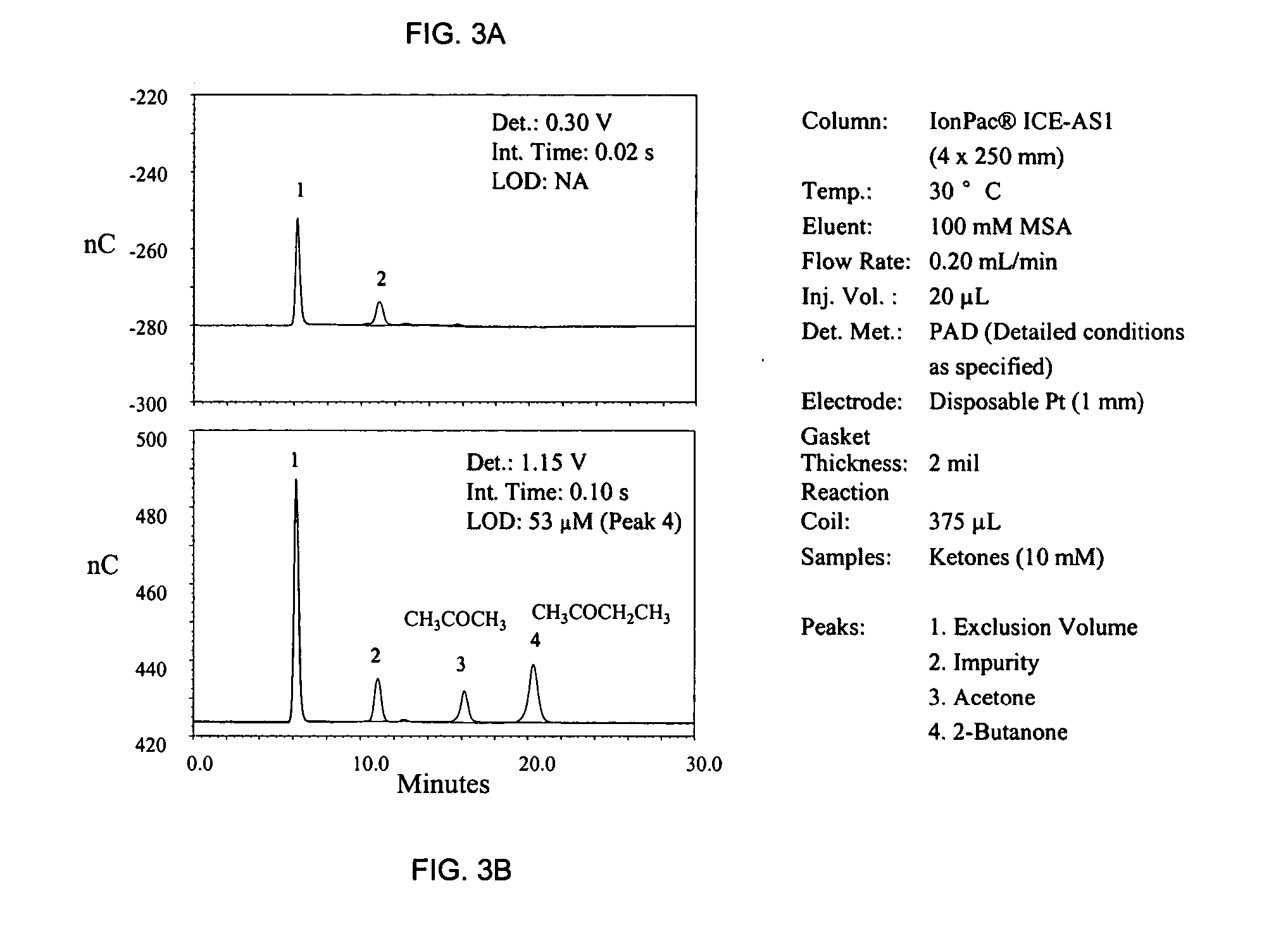
[0038]FIG. 3A shows a failed attempt to detect acetone and butanone by the prior art method (signal integration at 0.25 V). Only an unknown impurity, most likely an alcohol (peak 2) generates a detection response. Using the same waveform but with a signal integration at E2=1.15 V (FIG. 3B) both ketones are detected easily.

example 2

Elimination of Oxygen Dip

[0039] Using the prior art methodology, many chromatograms exhibit a feature called “oxygen dip” (negative peak 3, lower trace). Referring to FIG. 4, the new method (upper trace) minimizes the oxygen dip by signal integration at a potential which is far removed from the potential range of oxygen reduction to hydrogen peroxide. Even though the peak height of formaldehyde has been reduced by the new method (from 46 to 15 nC), the concurrent lowering of baseline noise (from 0.125 to 0.034 nC) improved the detection limit from 0.82 to 0.66 μM by the new method.

example 3

Minimizing Pulsations by the New Method

[0040] Referring to FIG. 5, the prior art approach and the new method generate a comparable size of response for sulfite anion (45 vs. 41 nC). However, the new methodology minimizes the regular baseline pulsations caused by oxygen insertion into the eluent flow by the pump pistons. The corresponding reduction in baseline noise (from 0.5 to 0.03 nC) leads to a marked improvement in the detection limits with the new method (from 0.34 to 0.02 ppm).


PUM


Abstract

In one embodiment, the present invention is directed to a pulsed electrochemical detection method comprising (a) flowing a liquid sample stream including at least one analyte past a working electrode in a flow-through cell; (b) applying at least three pulsed electrical potentials to the working electrode, (1) a first conditioning potential, (2) a second detection and oxidative cleaning potential, and (3) a third reductive cleaning potential, said second potential being higher than said first and third potentials and said first potential being higher than said third potential; and (c) detecting the output from said working electrode during the time period of applying said second potential.

Description

BACKGROUND OF THE INVENTION [0001] Direct electrochemical detection of aliphatic compounds with electroactive functional groups based on electrocatalytic reactions at noble metal electrodes, chiefly Au and Pt, is well known. Electrochemical detection is a widely accepted means of detection in liquid and ion chromatography. Electrochemical detectors operate by applying an electrical potential to the working electrode in a flow-through cell. Such detectors typically employ a cell of three electrodes, which are a working electrode, a reference electrode and a counter electrode. Typically, the methodology uses multi-step potential waveforms which incorporate a detection operation along with the anodic and cathodic cleaning of the electrode surface. In a typical potential waveform, anodic detection occurs at a first potential with current sampling at the end of the time period of applying the potential. The potential then is stepped to a second higher potential for oxidative cleaning of ...

Claims


Application Information

Patent Timeline
IPC IPC(8): G01N27/26
CPCG01N27/49
Inventor CHENG, JUNJANDIK, PETRLIU, XIAODONGPOHL, CHRISTOPHER A.
Owner DIONEX CORP
Why Eureka
Try Eureka