Reduced Friction Wind Turbine Apparatus and Method

a wind turbine and friction reduction technology, applied in the direction of renewable energy generation, electric generator control, greenhouse gas reduction, etc., can solve the problems of inconvenient operation, inconvenient maintenance, and inability to meet the needs of the customer, so as to reduce the drag force, increase the mass carried by the wind, and reduce the effect of drag

Inactive Publication Date: 2007-10-18
NATURAL FORCES
View PDF91 Cites 35 Cited by
  • Summary
  • Abstract
  • Description
  • Claims
  • Application Information

AI Technical Summary

Benefits of technology

[0016] This configuration reduces downward forces on the axle bearings. It reduces structural sagging away from the axle and provides a rigid superstructure to carry the vane assembly. It reduces potential drag forces between the rotating hull and the pool of fluid beneath it. The weight of the rotating hull gives the device kinetic energy and rotational stability. The Fixed Center Axle
[0038] This configuration allows the device to generate the maximum power achievable under any given wind speed. Placing the power house under the fluid pool eliminates surface structures that may interfere with wind flow into the shroud.

Problems solved by technology

The art has been limited by at least two technical difficulties.
One is the inconsistency of the wind.
A corollary to this problem is overcoming the frictional resistance to supporting equipment that is large and massive enough to drive larger generating turbines.
Vertical axle wind power generators have always been limited in their size (diameter) due to the forces of gravity.
Gravity also causes structural sag away from the axle.
Therefore, heavier construction methods are required to maintain rigidity as diameters increase, thereby increasing weight loads on the bearing.
These factors have limited the size (diameter) of vertical axle wind power generators and have therefore, limited the potential power output of these devices.
The presence of slow or still fluid at the outlet of the machine impedes the intake of further fluid by the machine, having a braking effect that decreases performance.
Each of these devices suffers from a restricted and inadequate provision for the outlet or venting of the fluid medium (air) away from the energy extraction component (a rotor).

Method used


Image

  • Reduced Friction Wind Turbine Apparatus and Method
  • Reduced Friction Wind Turbine Apparatus and Method
  • Reduced Friction Wind Turbine Apparatus and Method

Examples


Embodiment Construction

[0053] The following description of the preferred embodiment(s) is merely exemplary in nature and is in no way intended to limit the invention, its application, or uses.

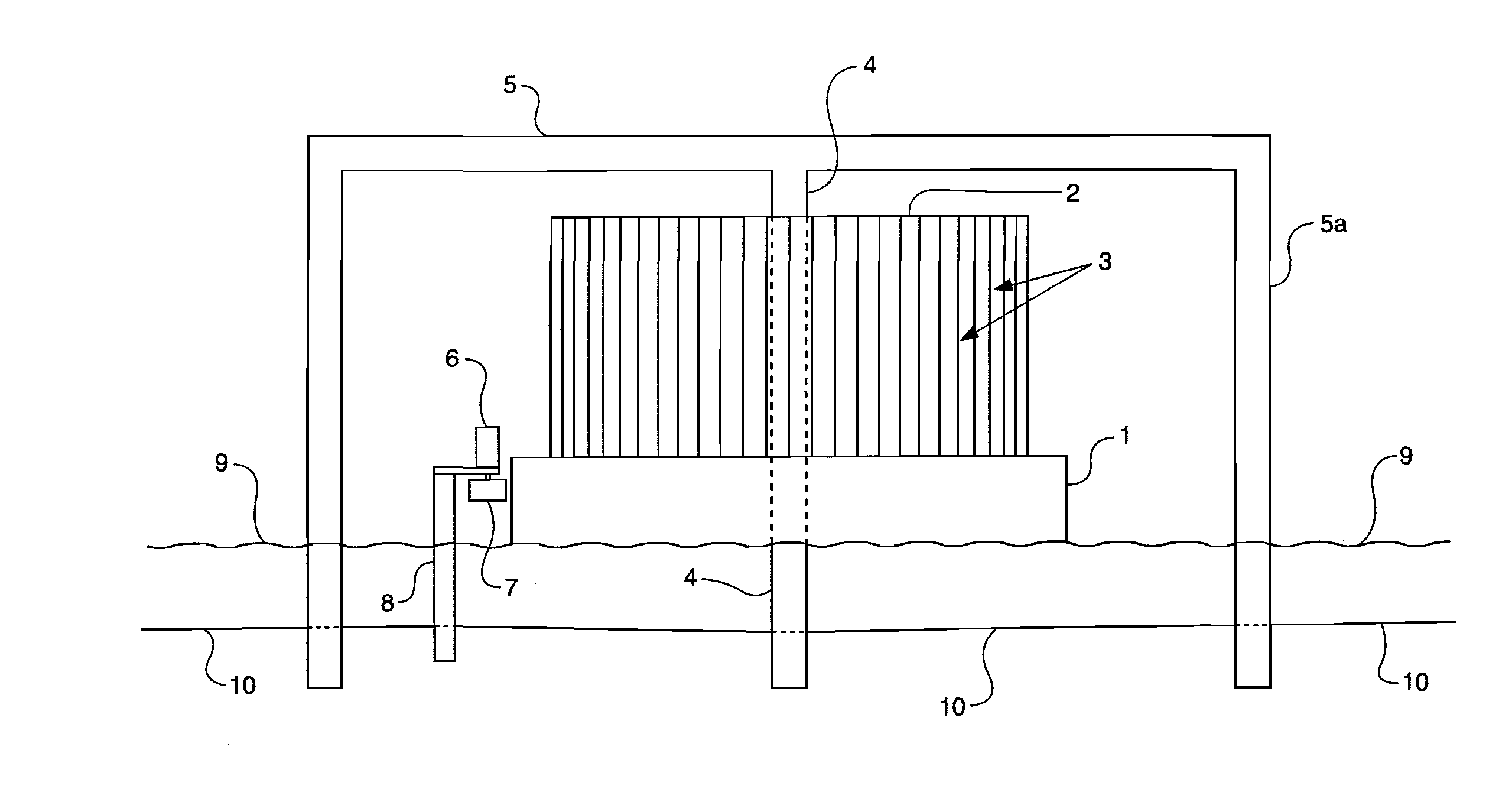
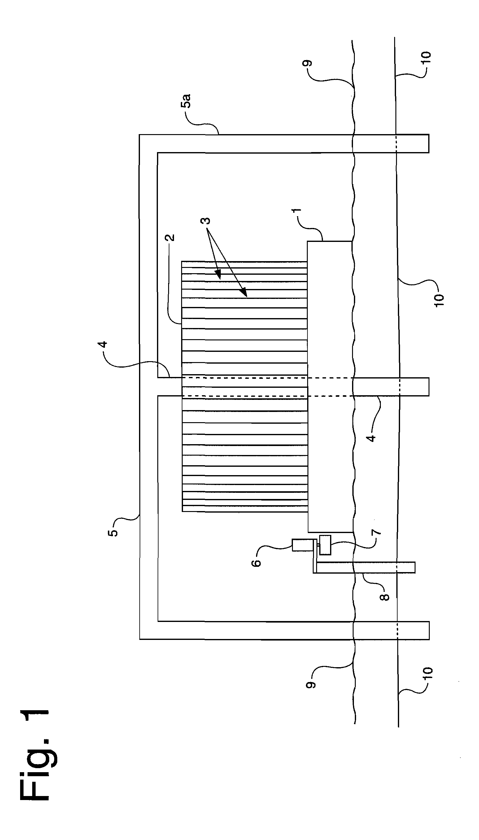
[0054] As illustrated in the drawings where like numerals represent like elements, FIGS. 1 and 2 depict the first embodiment of the present invention. A floating hull 1 is disposed to rest on a body of water 9. The body of water may be a preexisting naturally formed body water. Alternatively, the body of water 9 may be an artificially created pond, lagoon or the like disposed for support of the wind driven electricity generator.

[0055] Hull 1 has a positive displacement so that it floats on water. Hull 1 may be any size and weight, subject only to the limitation that it floats. Accordingly, hull 1 may be heavy and massive enough to serve as a flywheel. In the depicted embodiment, hull 1 is circular.

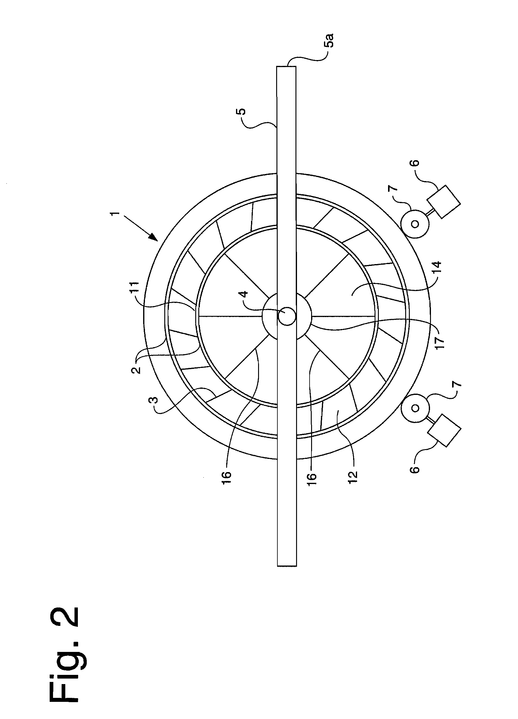
[0056] Hull 1 serves as a bottom mount for a plurality of vanes 3. The vanes are circularly arranged to form a fan. Th...


PUM


Abstract

A fluid flow energy capture device for power generation has a rotor with a substantially vertical axis and a plurality of vanes. A mount for the rotor allows the rotor to rotate in response to fluid flow such as wind contacting the plurality of vanes, and the mount puts the rotor in rotationally driving communication with a generator. The rotor has an open center which allows fluid communication from spaces between the vanes to above the rotor. A plurality of guide surfaces define channels that bias fluid flow to be tangential to the rotor.

Description

CROSS-REFERENCE TO RELATED APPLICATIONS [0001] The present application is a Continuation-in-Part of application Ser. No. 11 / 105,945 filed on Apr. 14, 2005.BACKGROUND OF THE INVENTION [0002] 1. Field of the Invention [0003] The present invention is in the field of wind driven electricity generation. [0004] 2. Related Art [0005] Wind as an alternate motive force for generating electricity has long provided an attractive alternative to conventional power generation techniques. The art has been limited by at least two technical difficulties. One is the inconsistency of the wind. Stated alternatively, there is a need in the art for extending the ability of wind driven electricity generation equipment to generate electricity beyond the time when the wind has dropped below velocities sufficient to turn generators. A corollary to this problem is overcoming the frictional resistance to supporting equipment that is large and massive enough to drive larger generating turbines. [0006] Both of t...

Claims


Application Information

Patent Timeline
Patent Type & Authority Applications(United States)
IPC IPC(8): F03D3/04
CPCF03D3/0472Y02E10/74F05B2240/93F03D3/0427F03D9/25F03D13/20Y02E10/727
Inventor PLATT, MICHAEL D.
Owner NATURAL FORCES
Why Eureka
Try Eureka