

Optical Near-Field Generator and Near-Field Optical Recording and Reproduction Apparatus
a generator and optical recording technology, applied in special recording techniques, instruments, nanoinformatics, etc., can solve problems such as energy loss and efficiency reduction, and achieve the effect of preventing the reduction of optical near-field intensity
- Summary
- Abstract
- Description
- Claims
- Application Information
AI Technical Summary
Benefits of technology
Problems solved by technology
Method used
Image

Examples
example 1
[0033]Initially, a case where a waveguide is used as a means to transmit incident light to a optical near-field element is described.
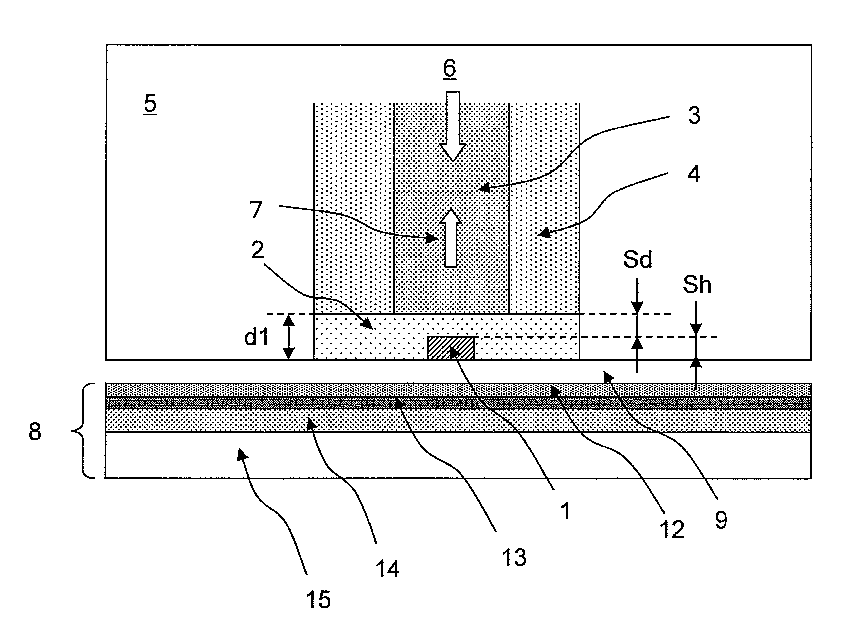
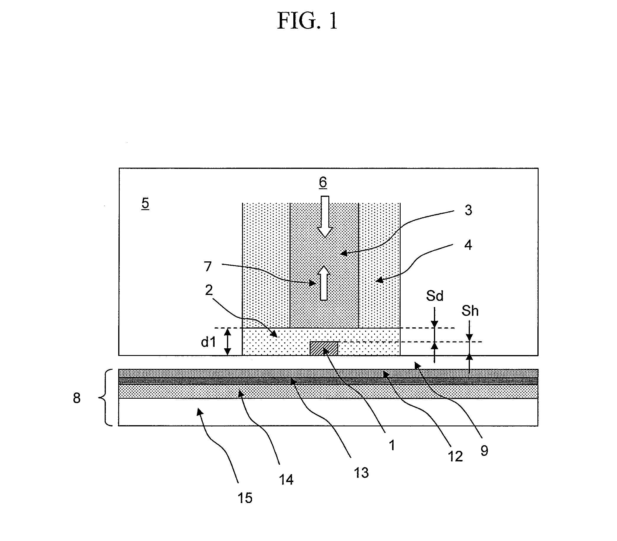
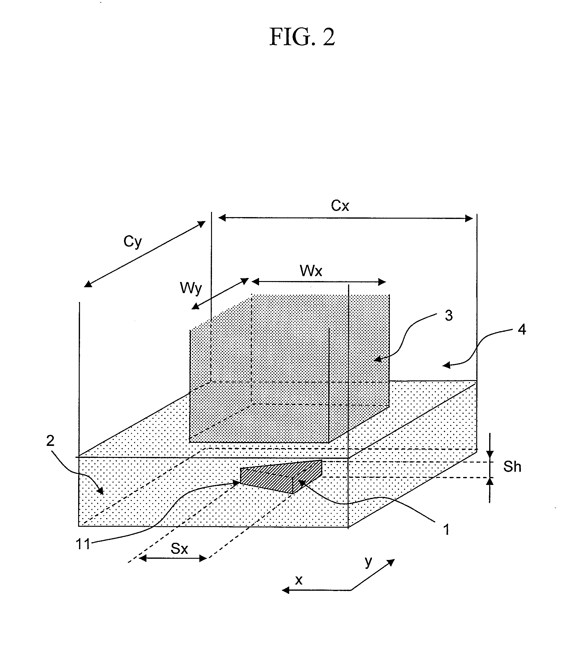
[0034]FIGS. 1 and 2 show an example of a head for a thermally assisted magnetic recording apparatus using a waveguide. In a slider 5, which constitutes a base for the head, a waveguide (composed of a core 3 and a cladding 4) for guiding light to a optical near-field generating element was formed. Below the waveguide, a scatterer 1 for producing optical near-field was formed. The material of the core 3 of the waveguide was Ta2O5 (refractive index=2.18), and the material of the cladding was SiO2. The waveguide had a square cross-section, with its widths Wx and Wy both measuring 500 nm. The cladding also had a square cross-section, with the widths Cx and Cy both measuring 1.0 μm.
[0035]As shown in FIG. 2, the scatterer 1 had a planar triangular shape, and its material was gold. The length Sx was 100 nm; thickness Sh was 50 nm; and the apex angle of an apex...
example 2
[0053]In the following, an example is described in which a lens is used as the means to transmit the incident light to the optical near-field element.
[0054]FIG. 11 shows the example in which a lens is used. In the present example, the lens consisted of a hemispheric lens 16 made of Bi4Ge3O12 (refractive index=2.23). The lens 16 was formed on the bottom surface of the slider 5, and the incident light 6 was caused to become incident on the lens such that the light is collected at the bottom surface of the hemispheric lens. The scatterer 1 was formed at the focal position on the bottom surface of the lens. The shape and material of the scatterer were the same as in the foregoing example. Around the scatterer 1, a hemispheric low refractive index portion 2 was formed of SiO2. It is necessary to reduce the thickness d1 of the low refractive index portion 2 but only to such an extent that the light-collecting characteristics of the lens do not deteriorate. For that purpose, the thickness ...
example 3
[0056]In the following, an example is described in which the optical near-field generator of the invention is combined with a single-pole head that is used in magnetic disc drives.
[0057]FIG. 13 shows a cross section of a recording head combining a single-pole head and a scatterer. On the surface of the slider 5, the scatterer 1 for producing optical near-field was formed, around which the low refractive index portion 2 was formed. Light was produced by a semiconductor laser with a wavelength 785 nm. The light emitted by the semiconductor laser was guided via a waveguide 22 to the slider 5. The light emerging from the waveguide 22 was collimated into parallel light by collimating lens 23. The light was folded by a mirror 24 and then coupled to a waveguide (consisting of a core 3 and a cladding 4) via a condenser lens 25, the waveguide connecting to the optical near-field generating element. A magnetic field was produced by a thin-film coil 17 and guided by a main magnetic pole 18 to ...
PUM
 Abstract
Description
Claims
Application Information