Microchip
a microchip and chip technology, applied in the field of microchips, can solve the problems of complicated handling of microchips, difficulty in continuously retaining liquid, limited material, etc., and achieve the effects of easy manufacturing, easy control, and easy refinemen
- Summary
- Abstract
- Description
- Claims
- Application Information
AI Technical Summary
Benefits of technology
Problems solved by technology
Method used
Image
Examples
first embodiment
[0068] (1) Structure around Valve
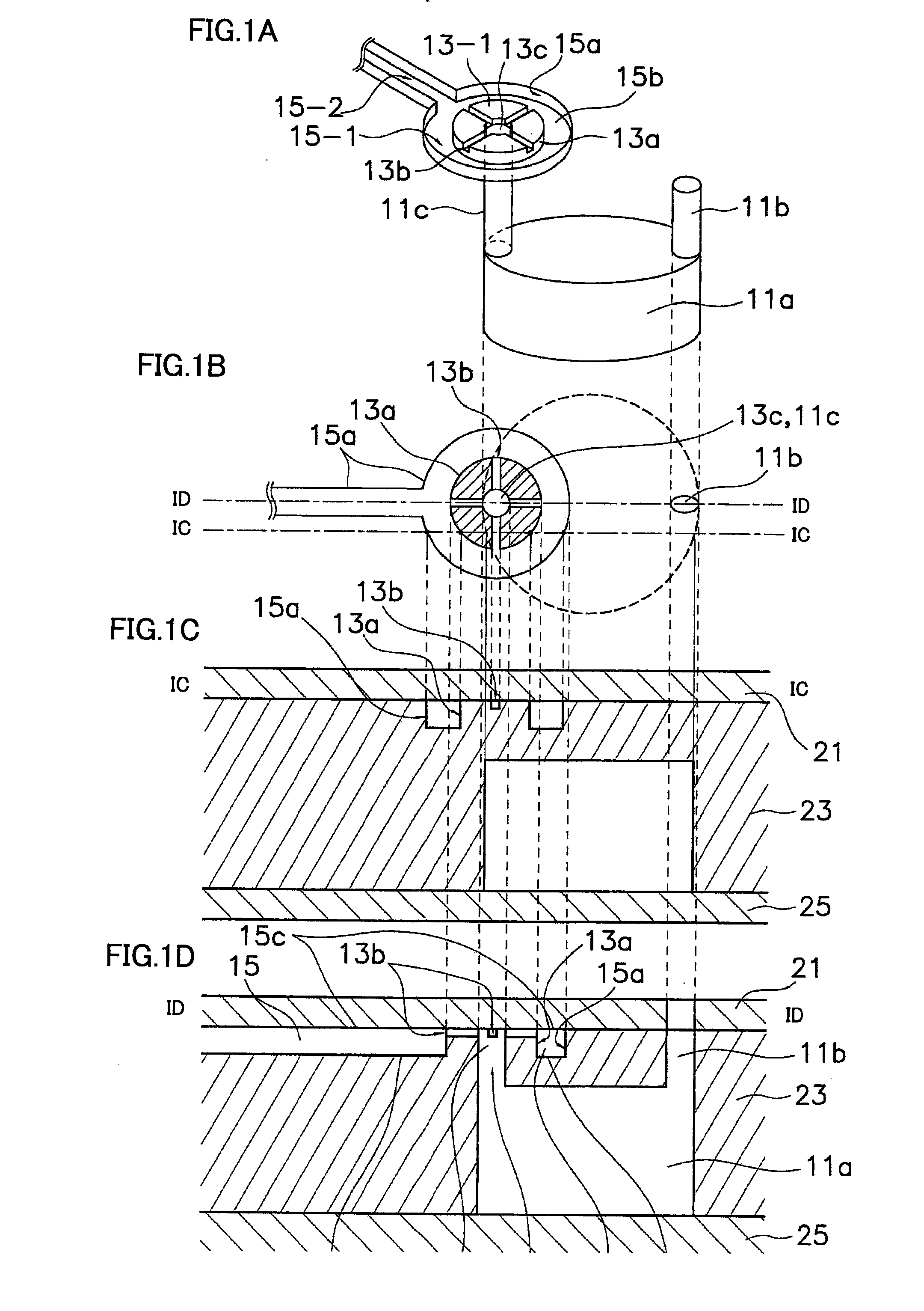
[0069]FIGS. 1A to 1D are explanatory diagrams around a valve in a microchip 100 according to the present invention, and FIG. 1A is a perspective view showing an exemplary structure of the valve in microchip 100 according to the present invention, FIG. 1B is a plan view showing the structure of the valve shown in FIG. 1A, FIG. 1C is a sectional view taken along the line IC-IC in FIG. 1B, and FIG. 1D is a sectional view taken along the line ID-ID in FIG. 1B.
[0070] Microchip 100 according to the present invention shown in FIGS. 1A to 1D is formed by three substrates, i.e., a first substrate 21, a second substrate 23 and a third substrate 25, and includes an introduction portion 11 receiving a liquid such as a sample or a reagent, an ejection portion 15 into which the liquid is ejected and a valve 13 connecting introduction portion 11 and ejection portion 15 with each other.
[0071] Introduction portion 11 has an introduction body 11a retaining the liqu...
second embodiment
[0181] (1) Structure around Valve
[0182]FIGS. 8A to 8D are explanatory diagrams around a valve in a microchip 200 according to the present invention, and FIG. 8A is a perspective view showing an exemplary structure of the valve in microchip 200 according to the present invention, FIG. 8B is a plan view showing the structure of the valve shown in FIG. 8A, FIG. 8C is a sectional view taken along the line VIIIC-VIIIC in FIG. 8B, and FIG. 8D is a sectional view taken along the line VIIID-VIIID in FIG. 8B.
[0183] Microchip 200 according to the present invention shown in FIGS. 8A to 8D is formed by two includes, i.e., first and second substrates 91 and 93, and includes an introduction portion 81 receiving a liquid such as a sample or a reagent, an ejection portion 85 into which the liquid is ejected and a valve 83 connecting introduction portion 81 and ejection portion 85 with each other.
[0184] Introduction portion 81 is so formed as to pass through first substrate 91, and connected to a...
third embodiment
[0209] (1) Structure around Valve
[0210]FIGS. 13A to 13D are explanatory diagrams around a valve of a microchip 300 according to the present invention, and FIG. 13A is a perspective view showing the structure of the valve in microchip 300 according to the present invention, FIG. 13B is a plan view showing the structure of the valve shown in FIG. 13A, FIG. 13C is a sectional view taken along the line XIIIC-XIIIC in FIG. 13B, and FIG. 13D is a sectional view taken along the line XIIID-XIIID in FIG. 13B.
[0211] Microchip 300 according to the present invention shown in FIGS. 13A to 13D is formed by three substrates, similarly to the first embodiment. More specifically, microchip 300 is formed by a first substrate 111, a second substrate 113 and a third substrate 115, and includes an introduction portion 101 receiving a liquid such as a sample or a reagent, an ejection portion 105 into which the liquid is ejected and a valve 103 connecting introduction portion 101 and ejection portion 10...
PUM
 Abstract
Description
Claims
Application Information
 - R&D
- Intellectual Property
- Life Sciences
- Materials
- Tech Scout
- Unparalleled Data Quality
- Higher Quality Content
- 60% Fewer Hallucinations
Browse by: Latest US Patents, China's latest patents, Technical Efficacy Thesaurus, Application Domain, Technology Topic, Popular Technical Reports.
© 2025 PatSnap. All rights reserved.Legal|Privacy policy|Modern Slavery Act Transparency Statement|Sitemap|About US| Contact US: help@patsnap.com


