Exhaust Gas Purification Apparatus

a technology of exhaust gas purification and purification apparatus, which is applied in the direction of lighting and heating apparatus, machines/engines, separation processes, etc., can solve the problems of no/sub>x /sub>can be reduced and purified, rarely has the exhaust gas in normal operation a chance to obtain a temperature level at which the particulates can be reduced, etc., to achieve the effect of preventing the fall of the nox reduction rate, enhancing low-temperature activity,

Inactive Publication Date: 2007-10-18
HINO MOTORS LTD
View PDF5 Cites 28 Cited by
  • Summary
  • Abstract
  • Description
  • Claims
  • Application Information

AI Technical Summary

Benefits of technology

[0042] According to an exhaust emission control device of the invention in its first aspect, the following excellent features and advantages will be obtained.
[0043] (I) In upstream oxidation catalyst arrangement for generation of highly oxidative NO2 to enhance low-temperature activity of the selective reduction catalyst, the paired oxidation catalysts are arranged in parallel with each other and upstream of said selective reduction catalyst, the amounts of the exhaust gas distributed to the respective oxidation catalysts being properly adjusted by the exhaust distribution means, so that the NO / NO2 ratio can be controlled to about 1-1.5 which is optimum for the reducing reaction of NOx. As a result, the excessive generation NO2 can be reliably suppressed to reliably prevent the falling of the NOx reduction rate, and the low-temperature activity of the selective reduction catalyst can be substantially enhanced in comparison with that in use of the single oxidation catalyst.
[0044] (II) As a countermeasure against the leaking ammonia which increases in an operation condition where the NOx reduction rate is less affected by the NO / NO2 ratio, the changeover from the first to the second passage pattern can be conducted to pass the exhaust gas in backflow through the selective reduction catalyst and respective oxidation catalysts. As a result, the ammonia passing through said selective reduction catalyst without reacted can be dealt with in the respective oxidation catalysts to prevent the ammonia from being discharged outside of a vehicle as it is, which needs no new or additional oxidation catalyst arranged against the leaking ammonia and preliminarily prevents the device from being deteriorated in mountability to the vehicle.
[0045] According to an exhaust emission control device of the invention in its second aspect, an excellent effect / advantage obtainable is such that, because of the NO / NO2 ratio being controlled by the plasma generator, the reduction of NOx can be satisfactorily conducted even if the urea water is added by the urea water addition means.
[0046] According to an exhaust emission control device of the invention in its third aspect, an excellent effects / advantages obtainable is such that, because of the NO / NO2 ratio being controlled by the plasma generator, the reduction of NOx can be conducted even when the urea water is added by the urea water addition means. At the same time, because of the soot of the particulate filter being oxidized by NO2, the affection of the soot in the particulate filter can be suppressed. Moreover, since the plasma generator is controlled on the temperature-area to temperature-area basis, the reduction of NOx and the oxidation of the soot can be conducted in consideration of the affection in terms of temperature in the respective temperature areas.

Problems solved by technology

However, the exhaust gas from the diesel engine in a normal operation condition rarely has a chance to obtain a temperature level at which the particulates ignite by themselves.
However, an active temperature area of such selective reduction catalyst is generally so small that, in fact, NOx can be reduced and purified only at a part of an exhaust temperature area of a diesel engine.
However, in a field of automobile where safety is hard to assure as to running with ammonia itself being loaded, researches have been made nowadays on use of nontoxic urea water as a reducing agent.

Method used


Image

  • Exhaust Gas Purification Apparatus
  • Exhaust Gas Purification Apparatus
  • Exhaust Gas Purification Apparatus

Examples


Embodiment Construction

[0118] An embodiment of the invention in its first aspect will be described in conjunction with the drawings.

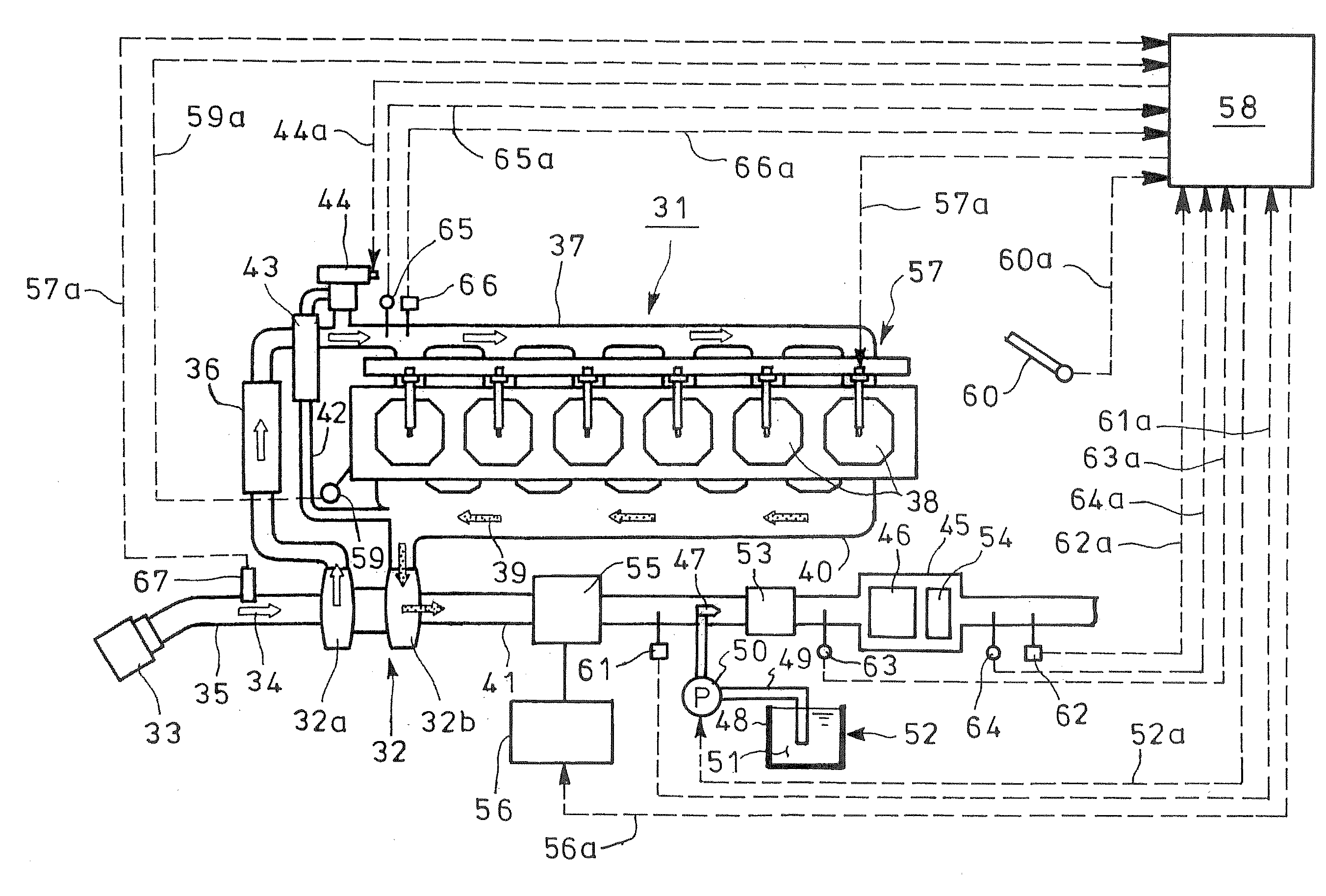
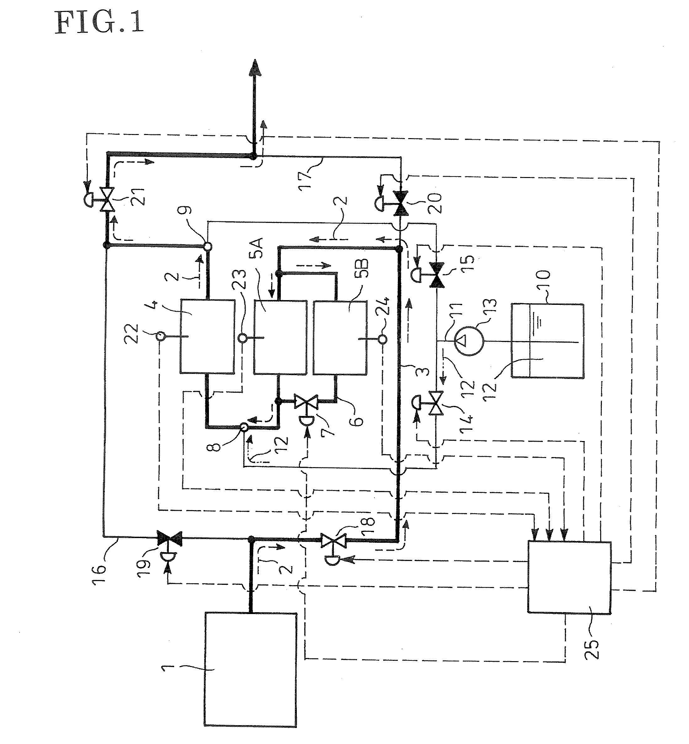
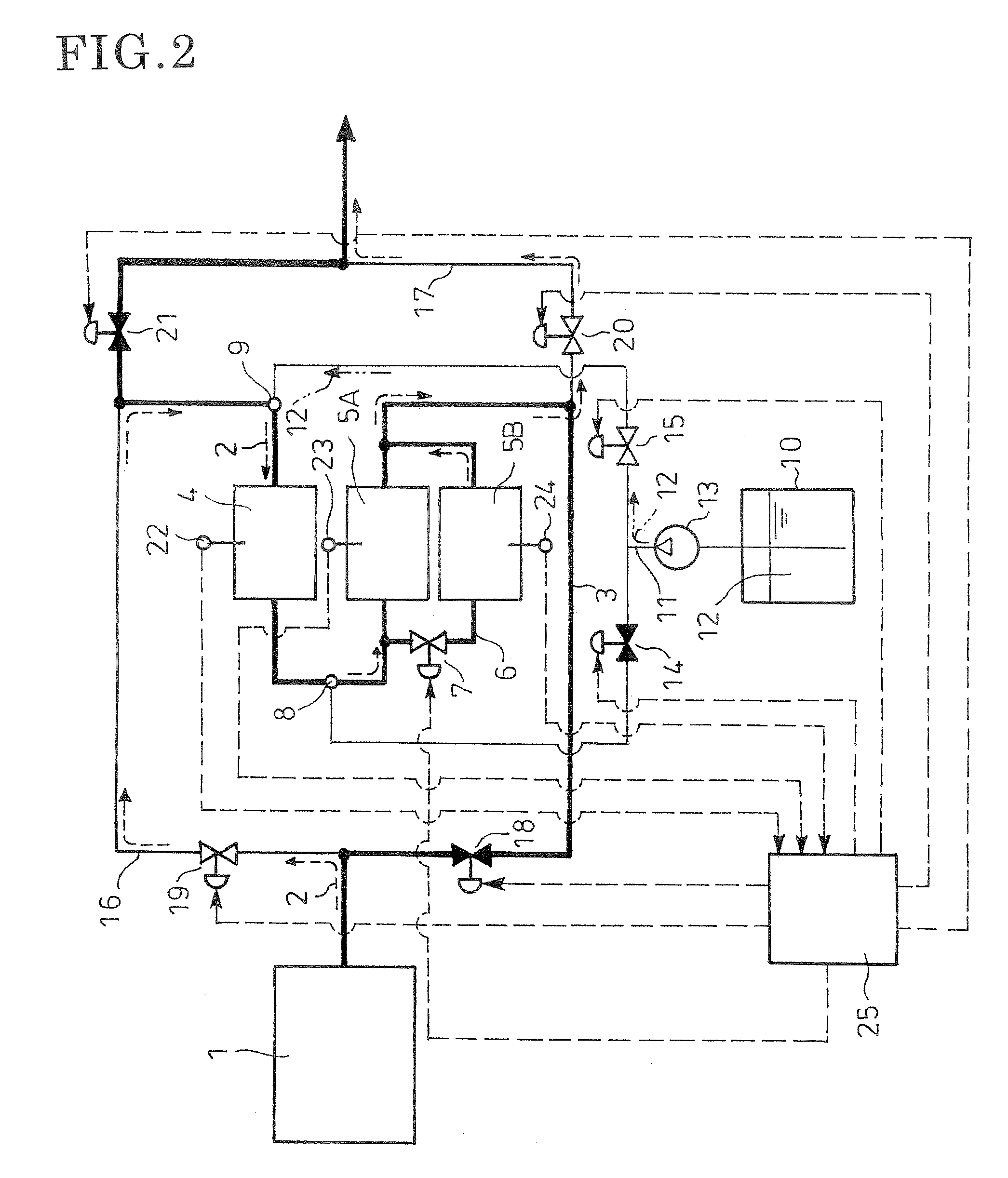
[0119]FIGS. 1 and 2 show the embodiment of the invention in its first aspect. In FIG. 1, reference numeral 1 denotes an engine which is a diesel engine. Exhaust gas 2 discharged from respective cylinders of the engine 1 passes through an exhaust pipe 3 (line shown by thick solid line in the figure; thickness of this line is for distinction between lines, not for indication of differences in passage diameter). Incorporated in the exhaust pipe 3 is a selective reduction catalyst 4 with a feature of selectively reacting NOx with ammonia even in the presence of oxygen.

[0120] Arranged upstream of the selective reduction catalyst 4 and in parallel with each other are two differently NO-oxidative oxidation catalysts 5A and 5B (highly and low NO-oxidative oxidation catalysts 5A and 5B, respectively). The exhaust gas 2 is parted by a divided passage 6 for the oxidation catalysts 5A ...


PUM

PropertyMeasurementUnit
temperatureaaaaaaaaaa

Abstract

Excessive generation NO2 by oxidation catalyst arrangement upstream of a selective reduction catalyst is suppressed to prevent falling of NOx reduction rate. A selective reduction catalyst 4 capable of selectively reacting NOx with ammonia even in the presence of oxygen is incorporated in an exhaust pipe 3 from an engine 1. A pair of oxidation catalysts 5A and 5B are arranged in parallel with each other and upstream of the selective reduction catalyst. In an operation condition with low exhaust temperature, amounts of the exhaust gas 2 distributed to the oxidation catalysts 5A and 5B are adjusted so as to make NO / NO2 ratio in the exhaust gas 2 to about 1-1.5. In an operation condition with higher exhaust temperature where the NOx reduction rate is less affected by the NO / NO2 ratio, as a countermeasure against increasing, leaking ammonia, passage changeover is conducted to pass the exhaust gas 2 in backflow through the selective reduction catalyst 4 and the oxidation catalysts 5A and 5B, so that ammonia passing through the selective reduction catalyst 4 without reacted is oxidized in the oxidation catalysts 5A and 5B.

Description

TECHNICAL FIELD [0001] The present invention relates to an exhaust emission control device applied to a diesel or other engine. BACKGROUND ART [0002] Particulates or particulate matter from a diesel engine is mainly constituted by carbonic soot and a soluble organic fraction (SOF) of high-boiling hydrocarbon and contains a trace of sulfate (misty sulfuric acid fraction). In order to suppress such kind of particles from being discharged to atmosphere, conventionally a particulate filter is incorporated in an exhaust pipe through which exhaust gas flows. [0003] This kind of particulate filter is constituted by a porous honeycomb structure made of ceramics such as cordierite and having lattice-like compartmentalized passages; alternate ones of the passages have plugged inlets and the remaining passages with unplugged open inlets are plugged at their outlets. Thus, only the exhaust gas passing through thin porous walls compartmentalizing the respective passages is discharged downstream....

Claims


Application Information

Patent Timeline
Patent Type & Authority Applications(United States)
IPC IPC(8): F01N3/00
CPCB01D53/9431B01D2251/2067B01D2259/818Y02T10/24F01N3/0814F01N3/206F01N3/035Y02T10/12
Inventor TSUMAGARI, ICHIROFURUKAWA, TAKATOSHITAKENAKA, YOSHIHIDEMACHIDA, KOICHISATO, SHINYA
Owner HINO MOTORS LTD
Why Eureka
Try Eureka