Catalytic diesel particulate filter and manufacturing method thereof

a technology of catalytic diesel and particulate filter, which is applied in the direction of physical/chemical process catalyst, metal/metal-oxide/metal-hydroxide catalyst, and separation process, etc. it can solve the problems of incomplete combustion of soot or unburned gas, insufficient soot combustion, and the need for ceria based catalyst to burn soot, so as to improve the low-temperature activity of the catalys

Inactive Publication Date: 2009-10-01
NGK INSULATORS LTD
View PDF8 Cites 18 Cited by
  • Summary
  • Abstract
  • Description
  • Claims
  • Application Information

AI Technical Summary

Benefits of technology

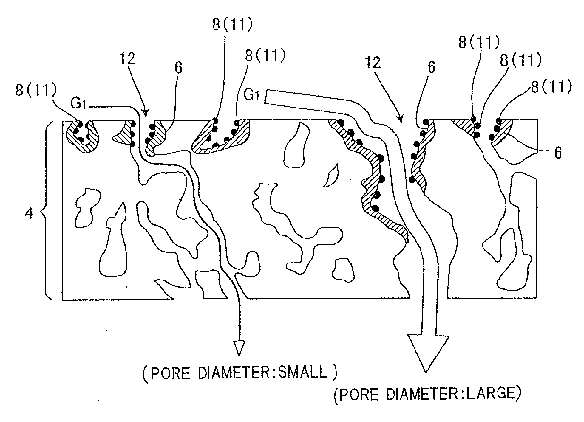
[0032]According to the present invention, since the ceria based catalyst coat layer including no noble metal and the noble metal based catalyst coat layer including a noble metal are separately present, it is possible to provide the diesel particulate filter that can take oxygen into particles from many portions through the noble metal, supply the taken-in oxygen to a portion having a low oxygen concentration, and improve low-temperature activity of the catalyst, and also provide the manufacturing method of a diesel particulate filter. Above all, it is possible to provide the diesel particulate filter that can further take oxygen into particles from many portions through the noble metal, further supply the taken-in oxygen to a portion having a low oxygen concentration, and can improve low-temperature activity of the catalyst since a double oxide of Ce, at least one alkaline-earth metal excluding Ce, and the noble metal is contained, and also provide the manufacturing method of a diesel particulate filter.

Problems solved by technology

Therefore, there occurs a problem that soot or an unburned gas is incompletely combusted.
That is, in the conventional honeycomb filter, since O2 is consumed for an on oxidative reaction of HC, CO, or NO with a Pt catalyst when the Pt based catalyst presents close to a ceria based catalyst, a concentration of O2 near the ceria based catalyst required to burn soot is low, and hence soot combustion is not sufficiently carried out.
Therefore, in a layer in which a catalyst based on a noble metal such as Pt presents close to a ceria based catalyst, a distance between these catalysts is too short, a soot amount combustion capability of the ceria based catalyst cannot be exploited to the utmost extent, and a soot combustion speed cannot be increased.
Thus, in the conventional honeycomb filter, since oxidation (combustion) of particulates cannot be sufficiently facilitated and the particulates in the exhaust gas cannot be reduced, the particulates are deposited on a surface of the partition wall on the exhaust gas inlet cell side in a relatively short time, a filter regenerative operation (an operation of removing the deposited particulates by, e.g., backwashing or heating) must be frequently carried out, and hence the conventional honeycomb filter is insufficient.
In Patent Document 1, an active oxygen generating particulate layer and a catalyst support layer are separately formed to prevent PM particles from being excessively deposited on a filter outer surface, but catalytic properties are not sufficiently exploited in the active oxygen generating particulate layer where soot is combusted due to a local reduction in oxygen concentration, a soot combustion speed is insufficient, and an improvement in regeneration efficiency may be also possibly obstructed.
However, such a structure is directly affected by a local oxygen concentration, and a soot high burnup function as a latent function of ceria cannot be sufficiently exploited.
That is, it should be said that this structure hardly improves a particulate combustion speed and cannot sufficiently enhance an exhaust gas purification capability or a regeneration efficiency.
As explained above, both Patent Documents 1 and 2 do not disclose a satisfactory countermeasure, the above-explained problem is not solved.
Besides, there is a technology that solves the problem by providing a providing a fibrous materia on an exhaust gas inlet side, but such a technology has a problem in durability and is insufficient to solve the above-explained problem, and hence a further improvement is demanded.

Method used


Image

  • Catalytic diesel particulate filter and manufacturing method thereof
  • Catalytic diesel particulate filter and manufacturing method thereof
  • Catalytic diesel particulate filter and manufacturing method thereof

Examples


example 1

Integral Structure SiC

[0107]A mixed powder containing 80 mass % of an SiC powder and 20 mass % of a metal Si powder was used as a raw material, methylcellulose, hydroxypropoxyl methylcellulose, a surfactant, and water were added to this mixed powder to fabricate a kneaded clay having plasticity, and the obtained kneaded clay was subjected to extrusion forming by an extruder, thereby being formed into a honeycomb shape having an integral structure SiC (a diameter of 144 mm and a length of 152 mm, 12 mil / 300 cpsi, a porosity of 50%, an average pore diameter of 15 μm). Then, this formed article was dried by using microwaves and hot air, and this honeycomb segment formed article was subjected to firing in an oxidizing atmosphere at a firing temperature of 1700° C. for 2 hours, thus obtaining a honeycomb formed article.

[0108]Subsequently, as a ceria based catalyst, ion-exchanged water, 6 g / L of a cerium oxide, 1 g / L of a zirconium acetate, and 3 g / L of a praseodymium oxide were mixed and...

example 2

Bonded Structure

[0114]A mixed powder containing 80 mass % of an SiC powder and 20 mass % of a metal Si powder was used as a raw material, methylcellulose, hydroxypropoxyl methylcellulose, a surfactant, and water were added to this mixed powder to fabricate a kneaded clay having plasticity, and the obtained kneaded clay was subjected to extrusion forming by an extruder, thereby obtaining sixteen 35-mm-square segments. Preliminary firing for degreasing was effected in an oxidizing atmosphere at 550° C. for 3 hours, the obtained honeycomb segments were entirely bonded by using a predetermined bonding material, and then firing was carried out in the oxidizing atmosphere at a firing temperature of 1400° C. for 2 hours. Additionally, an outer peripheral portion was ground to obtain a honeycomb segment of a diameter of 144 mm and a length of 152 mm. A cell structure of the obtained honeycomb segment has 12 mil, 300 cpsi, a porosity of 50%, and an average pore diameter of 15 μm.

[0115]Then, ...

example 3

Structure having High Inlet Cell Capacity

[0116]A mixed powder containing 80 mass % of an SiC powder and 20 mass % of a metal Si powder was used as a raw material, methylcellulose, hydroxypropoxyl methylcellulose, a surfactant, and water were added to this mixed powder to fabricate a kneaded clay having plasticity, and the obtained kneaded clay was subjected to extrusion forming by an extruder, thereby being formed into a honeycomb shape having an integral structure SiC (a diameter of 144 mm and a length of 152 mm, a porosity of 50%, an average pore diameter of 15 μm). Then, this formed article was dried by using microwaves and hot air, and this honeycomb segment formed article was subjected to firing in an oxidizing atmosphere at a firing temperature of 1700° C. for 2 hours, thus obtaining a honeycomb formed article. There was obtained a honeycomb structure having a cell structure that has an octagonal shape at an inlet (a gas inlet), a square shape at an outlet (a gas outlet), 12 m...


PUM

PropertyMeasurementUnit
pore diameteraaaaaaaaaa
porosityaaaaaaaaaa
diameteraaaaaaaaaa

Abstract

There are provided a catalytic diesel particulate filter that is arranged in an exhaust system of a diesel engine and includes a catalyst that burns a particulate matter contained in an exhaust gas from the diesel engine, wherein the catalyst is configured in such a manner that a ceria based catalyst coat layer 6 containing no noble metal and a noble metal based catalyst coat layer 11 containing a noble metal are separately provided on a substrate constituted of a honeycomb structure, and a method for producing the same.

Description

BACKGROUND OF THE INVENTION[0001]1. Field of the Invention[0002]The present invention relates to a catalytic diesel particulate filter that is utilize to collect or purify particulates included in an exhaust gas emitted from an internal combustion engine such as a diesel engine or various kinds of combustion apparatuses, and a manufacturing method of the catalytic diesel particulate filter.[0003]2. Description of the Related Art[0004]An exhaust gas emitted from an internal combustion engine such as a diesel engine or various kinds of combustion apparatuses (which will be appropriately referred to as “e.g., an internal combustion engine” hereinafter) contains a large amount of particulate materials (which will be appropriately referred to as “particulate matters” or “PMs” hereinafter) including soot (graphite) as a main constituent. Since environmental contamination occurs when the particulates are discharged into air as they are, a filter that collects particulates is generally prov...

Claims


Application Information

Patent Timeline
Patent Type & Authority Applications(United States)
IPC IPC(8): B01J27/224B01J23/10B01J21/08B01J21/14
CPCB01D53/944B01D2255/1021B01J2523/00B01J37/0248B01J37/0244B01J23/63B01J23/002B01D2255/206B01D2255/9022B01D2255/908B01D2258/012B01J2523/31B01J2523/3712B01J2523/3718B01J2523/48B01J2523/828
Inventor MIZUTANI, TAKASHISAITO, CHIKA
Owner NGK INSULATORS LTD
Why Eureka
Try Eureka