Knife sharpening apparatus

a sharpening apparatus and blade technology, applied in the field of blade sharpening apparatus, can solve the problems of accelerated belt wear, accelerated belt wear, and increased belt tension, so as to reduce the tension of the belt, increase the tension, and increase the force

Inactive Publication Date: 2007-10-18
FUCHS RICHARD W
View PDF22 Cites 15 Cited by
  • Summary
  • Abstract
  • Description
  • Claims
  • Application Information

AI Technical Summary

Benefits of technology

[0014] In addition, when the cutting edge traverses the guide slot in a direction away from the endless belt, the force decreases and the support member and biasing member respond to the decreasing force to pivot the support member toward the engaged position and increase tension in the belt such that the belt rotates along the path toward the first rotational speed.
[0015] One aspect of the present invention includes a method for sharpening a cutting edge of a cutting tool, the method includes the step of providing an endless belt rotating in a path about a plurality of pulleys. At least one of the pulleys is affixed to a support member pivoting about a rotational axis between an engaged position and a disengaged position. The method also includes engaging the belt with the cutting edge to impart a force on the belt and sharpen the cutting edge. When the force is at and below a first threshold, the support member is in the engaged position and the endless belt rotates at a first rotational speed. The force is then increased above the first threshold toward a second threshold. In response to the increased force, the support member rotates from the engaged position toward the disengaged position, decreasing a tension in the belt such that the belt rotates at a second rotational speed that is less than the first rotational speed.

Problems solved by technology

If the applied force is too great, the cutting edge overheats resulting in a change in the microstructure of the cutting edge and a reduction of the surface hardness of the cutting edge.
In addition, excessive force applied to the belt by the cutting edge can cause accelerated belt wear.
On the other hand, if the applied force is inadequate to keep the cutting edge in contact with the belt, the sharpening procedure may require an undue amount of time.
Therefore, angular positioning of the knife relative to the belt affects sharpening quality.
However, this does not preclude the possibility of the knife being accidentally or intentionally moved beyond the index mark, creating overheating of the cutting edge, belt damage and other problems.
However, the unloader discs can wear and therefore become less effective.
In such knife sharpeners, overheating of and damage to the cutting edge can occur quickly when excessive force is applied, because the belt does not slow or stop relative to the force applied.
If the two housing portions are rotated apart from one another while the belt is operating, rotating parts thereof are exposed and a safety hazard can result.
Such knife sharpeners have not been frequently used by individual home owners because the size and weight of the knife sharpener makes it impractical for home countertop use.
Moreover, such units generally operate on 120 volt A / C power which requires the knife sharpener to be stationed within access to a suitable power supply and requires use of relatively expensive motors.
However, slight alignment errors in the relation of the axes of the pulleys to one another or slight variations in the lengths of the edges of the belt can cause the belt to move off track by shifting laterally to one side or the other from the desired centered position.
In some instances, the belt may run completely off of the pulleys or rub against a wall or other structure of the machine located adjacent one or both of the pulleys or the belt, resulting in the shortening of belt and / or machine life.
Such adjustment means have however tended to pose various problems of their own, including being of a complex, expensive construction and being difficult to operate or fine tune during operation.
Prior art methods and systems for addressing these needs are either too expensive, too complicated, ineffective or a combination of all of these.

Method used


Image

  • Knife sharpening apparatus
  • Knife sharpening apparatus
  • Knife sharpening apparatus

Examples


Embodiment Construction

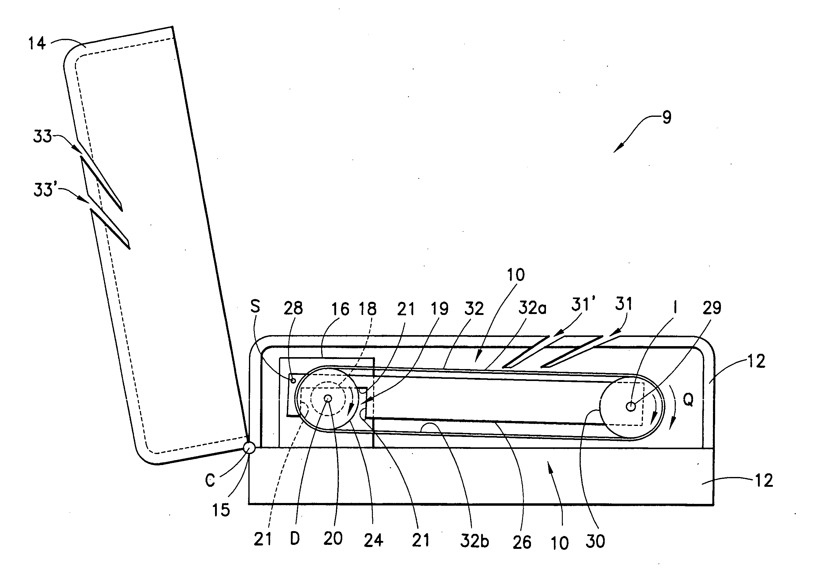
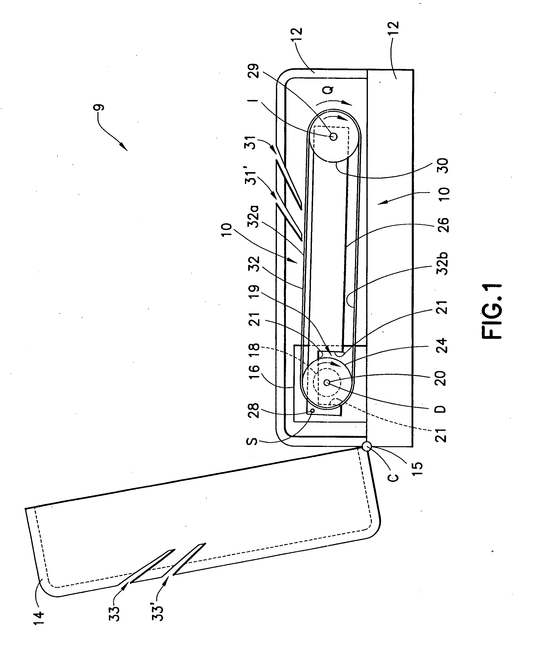
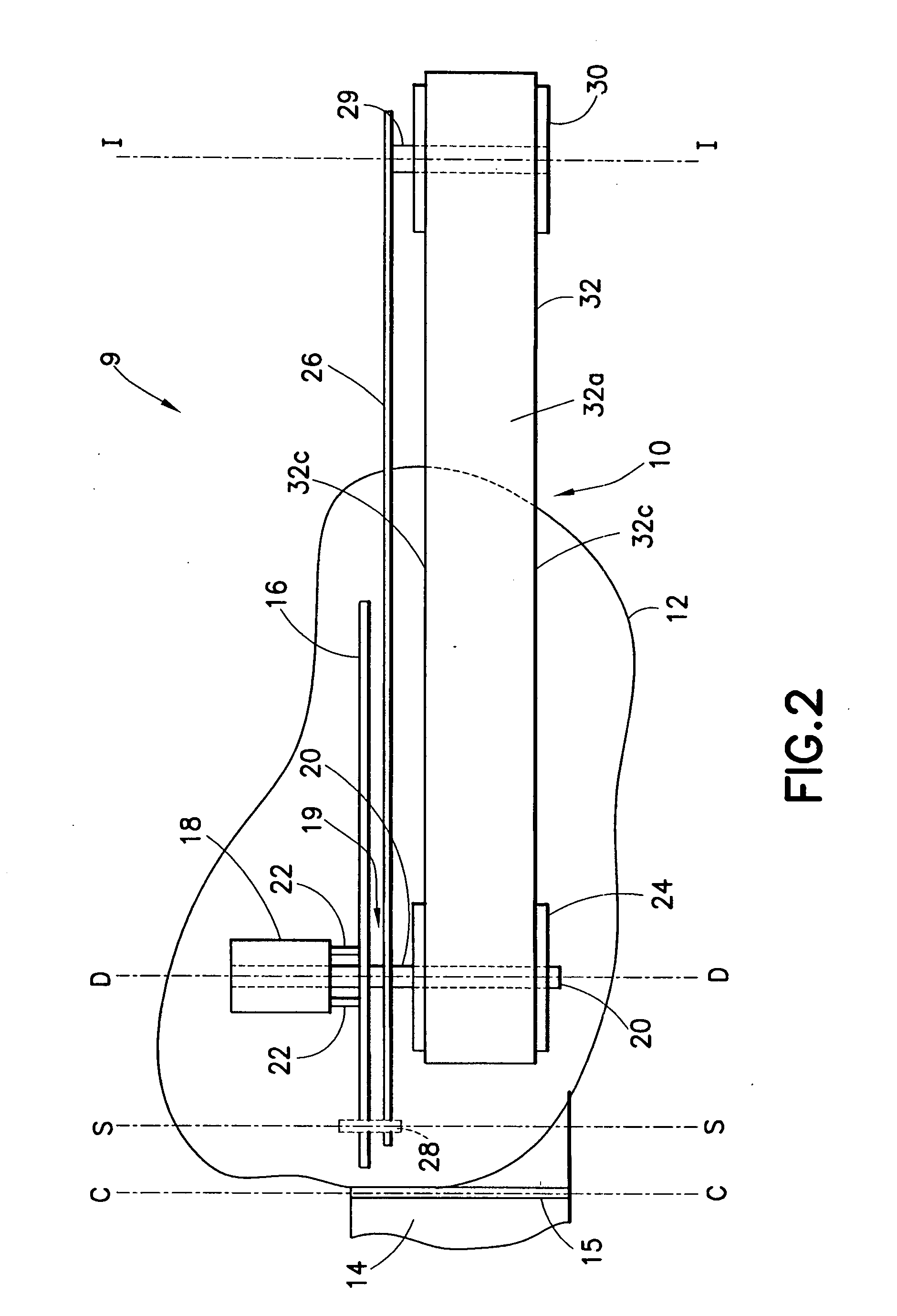
[0047]FIGS. 1 and 2 illustrate a sharpening apparatus, indicated generally at 9, for sharpening knives and other cutting tools having at least one elongated edge. The knife sharpening apparatus 9 includes a frame 12 and a cover 14 hingedly coupled to the frame by a hinge device 15, for rotational movement about a cover rotational axis C between an open and a closed position. In one embodiment, the hinged device 15 is releasable, enabling the cover 14 to be removed from the frame 12. In FIG. 1 the cover 14 is shown in an open position. The frame 12 and cover 14 collectively house a pulley and belt assembly 10 including a drive pulley 24, an idler pulley 30 and an endless belt 32 mounted for rotation between the pulleys. The frame 12 includes two frame guide slots segments 31, 31′ and the cover 14 includes two cover guide slot segments 33, 33′. When the cover 14 is closed against the frame 12, the frame guide slot segments 31, 31′ and the cover guide slot segments 33, 33′ cooperate to...


PUM

PropertyMeasurementUnit
angleaaaaaaaaaa
angleaaaaaaaaaa
angleaaaaaaaaaa

Abstract

A sharpening apparatus having at least one guide slot, a drive pulley drivingly coupled to a frame and at least one idler pulley rotatably coupled to a support member. The support member is pivotably coupled to the frame. The apparatus includes an endless abrading belt rotatable in a path over the drive pulley and the at least one idler pulley and a biasing member coupled to the frame for biasing the support member toward an engaged position. Pivotal movement of the support member adjusts tension in the belt. A tool is traversed into the guide slot for sharpening a cutting edge thereof. The belt and support member respond to application and release of a force applied to the belt by the cutting edge to decrease and increase, respectively, belt speed to preclude overheating of the cutting edge and damage to the belt and cutting edge.

Description

[0001] This application claims priority from provisional application Ser. No. 60 / 791,977, filed Apr. 13, 2006, the disclosure of which is incorporated by reference herein, in its entirety.FIELD OF THE INVENTION [0002] The present invention is generally directed to a sharpening apparatus for cutting tools and is more specifically directed to a knife sharpening apparatus having an abrading belt that is capable of sharpening a cutting edge of knives and other cutting tools without overheating or damaging the cutting edge. BACKGROUND OF THE INVENTION [0003] Knife sharpening apparatuses of the type having an abrasive belt and means for supporting and driving the belt along an endless path are well known. It is also well known to use such machines for sharpening knives and other tools having elongated cutting edges. For a knife or the like to be optimally sharpened with such machines the cutting edge must engage the abrasive belt at an appropriate angle and with an appropriate amount of f...

Claims


Application Information

Patent Timeline
Patent Type & Authority Applications(United States)
IPC IPC(8): B24B1/00B24B21/00
CPCB24B3/54B24B21/20B24B21/002
Inventor FUCHS, RICHARD W.
Owner FUCHS RICHARD W
Why Eureka
Try Eureka