Fluid machine, rankine cycle and control method

a technology of rankine cycle and control method, applied in the field of fluid, can solve the problems of large device cost and large setting space, and achieve the effect of reducing the execution of useless control

Inactive Publication Date: 2007-10-25
DENSO CORP +1
View PDF6 Cites 17 Cited by
  • Summary
  • Abstract
  • Description
  • Claims
  • Application Information

AI Technical Summary

Benefits of technology

[0009] With this arrangement, the lubricant oil can be fed to the sliding portion by control of the sliding surface pressure by the sliding surface pressure adjustment means, which can provide a fluid machine for feeding the lubricant oil to the sliding portion with a simple structure without needing a complicated control process.
[0026] According to a seventh example of the present invention, a control method of a Rankine cycle includes a first step of guiding lubricant oil to a sliding surface of an expansion unit by allowing the working fluid to flow by an operation of a pump with a high-pressure portion of the expansion unit communicated with a low-pressure portion thereof by a communication passage, and a second step of closing the communication passage. This can provide a control method of a Rankine cycle together with the feed of the lubricant oil to the sliding portion and the transfer to a normal operation without needing complicated control.

Problems solved by technology

This results in increased number of components constructing a fluid machine device, thereby needing a large setting space and large cost for the device.

Method used


Image

  • Fluid machine, rankine cycle and control method
  • Fluid machine, rankine cycle and control method
  • Fluid machine, rankine cycle and control method

Examples


first embodiment

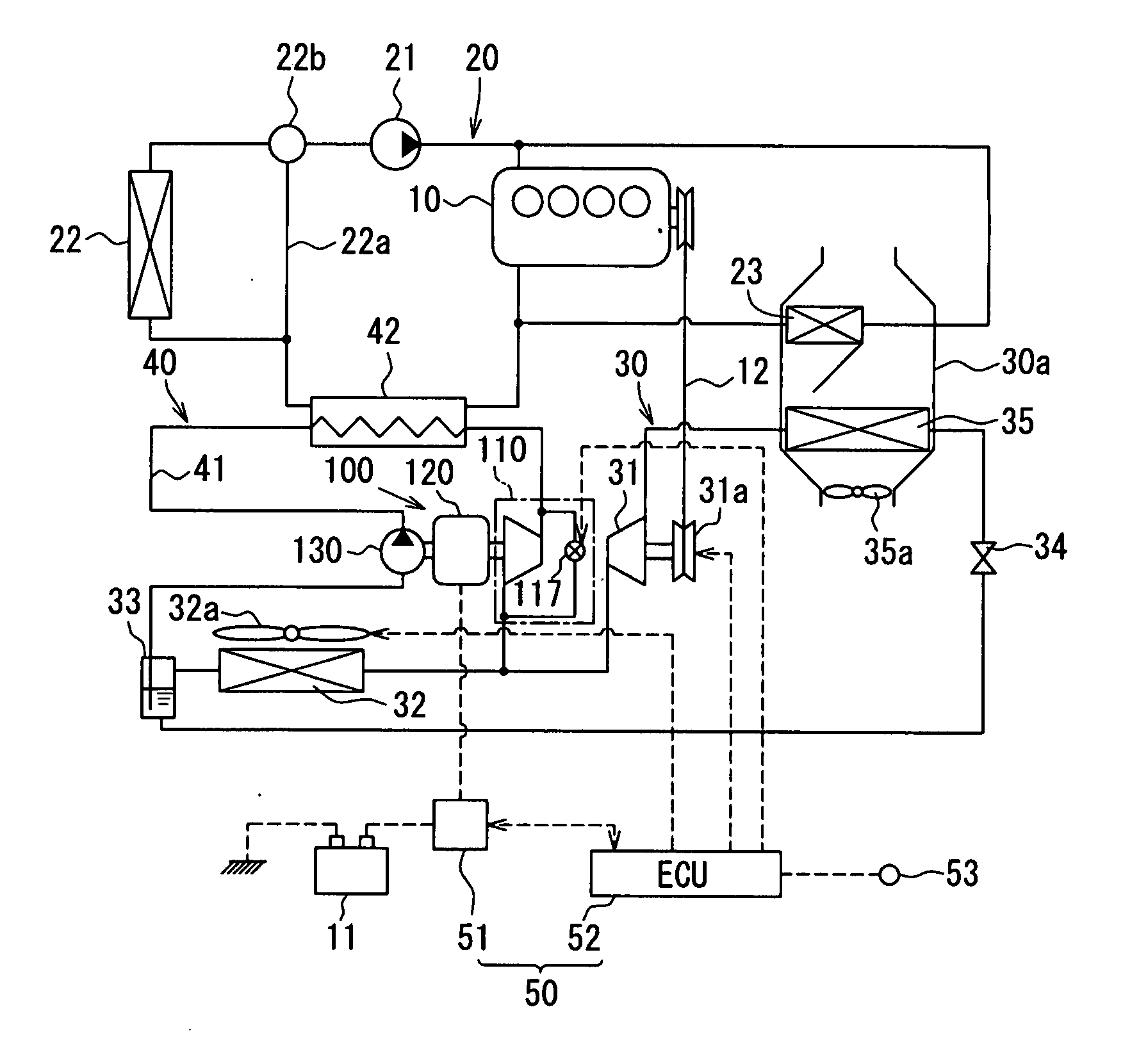
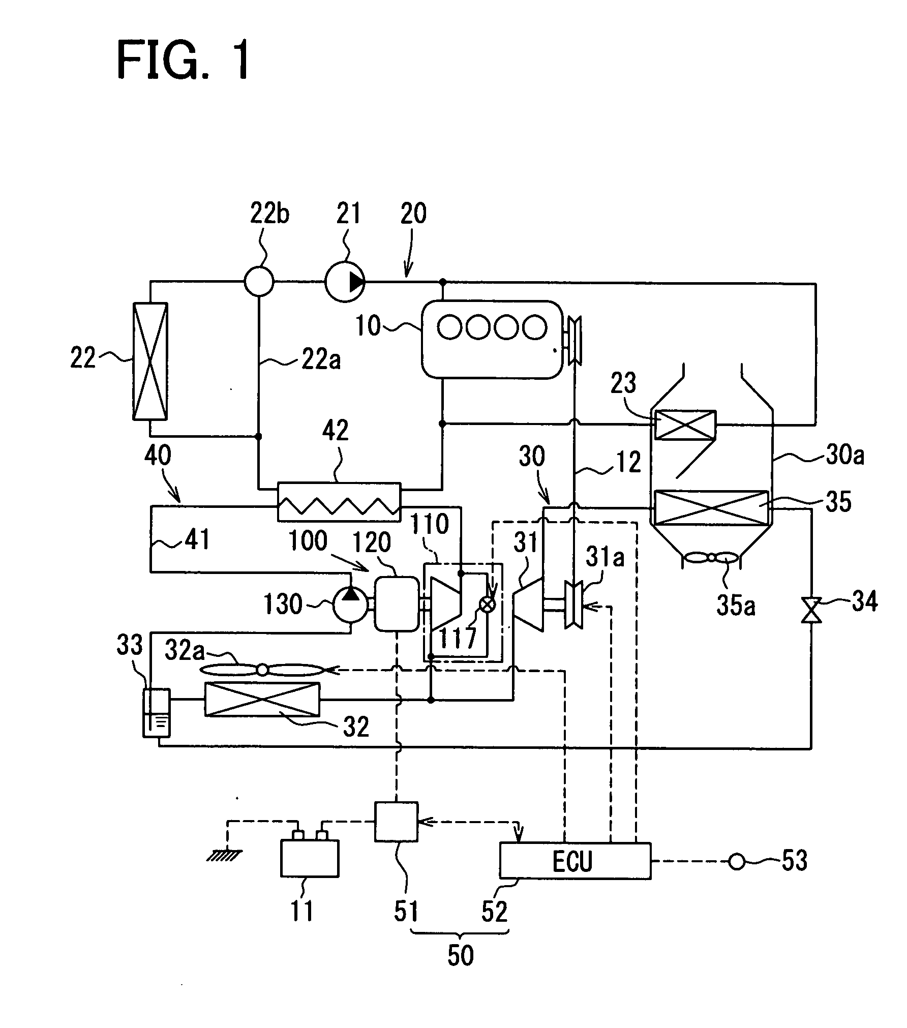
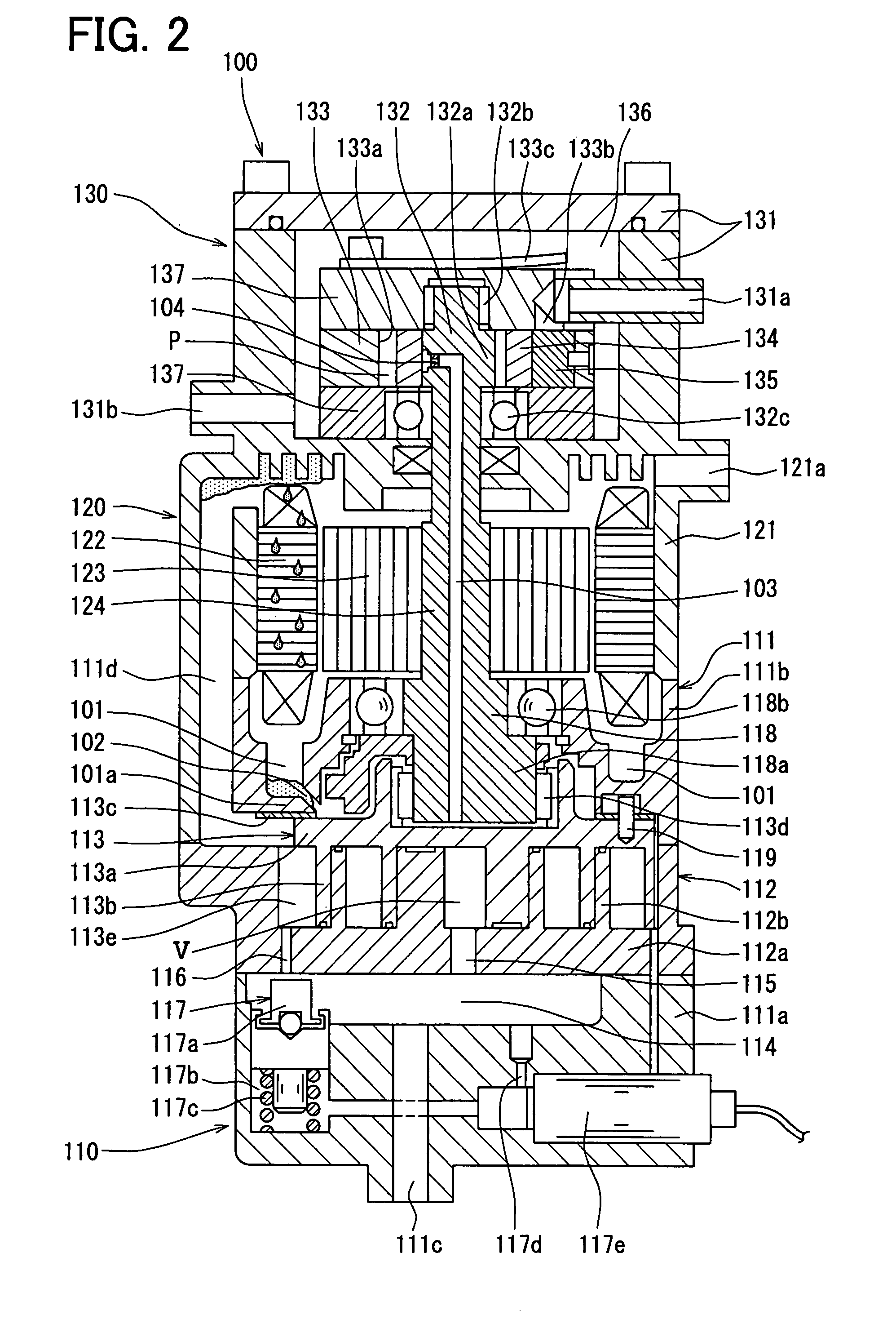
[0038] In this embodiment, a refrigerant-pump integrated type expansion generator (hereinafter referred to as a pump expansion generator) 100 employed as one example of a fluid machine of the present invention will be described below. The pump expansion generator 100 is used in a Rankine cycle 40 which uses a condenser 32 and a vapor-liquid separator 33 in common with a refrigeration cycle 30 for a vehicle. The pump expansion generator 100 has an expansion unit 110 serving as fluidization means, a motor generator 120 which is a portion driven by the expansion unit 110 and serving an electric motor and a generator, and a refrigerant pump 130, all of which are formed integrally.

[0039] This embodiment will be described below with reference to FIGS. 1, 2, 4, and 5. FIG. 1 shows an entire system structure. The refrigeration cycle 30 is to use cold heat and hot heat for air conditioning by allowing heat on the low-temperature side to be transferred to the high-temperature side. The refri...

second embodiment

[0104] A fluid machine of this embodiment will be described below using FIGS. 3 and 4. FIG. 3 is a sectional view showing the structure of a refrigerant-pump integrated type expansion generator of this embodiment (hereinafter referred to as a pump expansion generator100A). FIG. 4 shows the flowchart of the operation control procedure of the pump expansion generator 100 as described in the first embodiment. However, the operation control of the pump expansion generator 100A of this embodiment is also based on this flowchart.

[0105] As shown in FIG. 3, the pump expansion generator 100A of this embodiment differs from the pump expansion generator 100 of the above-mentioned first embodiment in the structure of a motor generator 120A, which includes a centrifugal separator 144 for separating lubricant oil from refrigerant using a centrifugal force as separation means. The structure, operation, and control of each component are the same as those of the pump expansion generator 100 of the ...

third embodiment

[0110] A fluid machine of this embodiment will be described below using FIGS. 6 and 8. FIG. 6 is a sectional view showing the structure of a refrigerant pump integrated expansion generator of this embodiment (hereinafter referred to as a pump expansion generator 100). FIG. 8 shows a flowchart of an operation control method of the pump expansion generator 100 of this embodiment.

[0111] As shown in FIG. 6, the pump expansion generator 100 of this embodiment differs from the pump expansion generator 100 of the above-mentioned first embodiment shown in FIG. 2 in provision of an oil sensor 148 serving as oil detection means for detecting the presence of the lubricant oil in the oil reservoir 101. The structures and operations of other parts of this embodiment are the same as those of the pump expansion generator 100 of the first embodiment.

[0112] The operation control method of the pump expansion generator 100 of this embodiment includes step S132 shown in FIG. 8, which is a modificatio...


PUM


Abstract

A fluid machine includes a fluidization portion for compressing or expanding a working fluid which is heated to be brought into a vapor phase state after circulating in a cycle, an oil storage portion for storing therein lubricant oil for lubricating a sliding surface of the fluidization portion, a lubricant oil feed passage for guiding the lubricant oil stored in the oil storage portion to a sliding portion of the fluidization portion by a flow of the working fluid, and a sliding surface pressure adjustment portion that is controlled to adjust a sliding surface pressure of the sliding portion. The working fluid flows inside the machine with the sliding surface pressure of the sliding portion decreased as compared with that in a normal operation of the fluidization portion by the sliding surface pressure adjustment portion, and thereafter the decreasing of the sliding surface pressure by the sliding surface pressure adjustment portion is released.

Description

CROSS REFERENCE TO RELATED APPLICATION [0001] This application is based on Japanese Patent Applications No. 2006-113741 filed on Apr. 17, 2006, and No. 2006-348336 filed on Dec. 25, 2006, the contents of which are incorporated herein by reference in its entirety. BACKGROUND OF THE PRESENT INVENTION [0002] 1. Field of the Present Invention [0003] The present invention relates to a fluid machine for separating lubricant oil from a working fluid and for feeding the oil to a part requiring lubrication, a Rankine cycle using the same, and a control method for the same. [0004] 2. Description of the Related Art [0005] A conventional fluid machine include a heat exchanger for introducing a high heat source into an oil reservoir of an oil separator via piping, in a Rankine cycle including an expansion unit, a condenser, a refrigerant pump, a steam generator, and the oil separator (as disclosed in, for example, JP-A-58-32908). The oil containing liquid refrigerant in the oil reservoir is appr...

Claims


Application Information

Patent Timeline
Patent Type & Authority Applications(United States)
IPC IPC(8): F01K13/00F01K25/06
CPCB60H1/3214B60H2001/3238F01C11/008F25B27/02F01K23/065F01K25/08F01K13/02Y02A30/274
Inventor UNO, KEIICHIASA, HIRONORIUTIDA, KAZUHIDE
Owner DENSO CORP
Why Eureka
Try Eureka