Silicon refining process

a technology of silicon refining and process, which is applied in the direction of silicon compounds, chemistry apparatus and processes, silicates, etc., can solve the problems of increasing the cost and economic viability of solar cells, and the silicon required for a solar cell is more expensive than the required, so as to reduce the susceptibility of the nation's generation capacity, reduce the cost of manufacturing a solar cell, and change the way a large portion of electrical power is

Inactive Publication Date: 2007-10-25
THE ARIZONA BOARD OF REGENTS ON BEHALF OF THE UNIV OF ARIZONA
View PDF9 Cites 28 Cited by
  • Summary
  • Abstract
  • Description
  • Claims
  • Application Information

AI Technical Summary

Benefits of technology

[0009] The process may require pretreatment of the molten silicon to remove dissolved oxygen (deoxidation). This can be done, for example, by heating the molten silicon, or by a combination of heating and vacuum treatment of the molten silicon, to volatilize the dissolved oxygen as silicon monoxide (SiO) and carbon monoxide (CO), the latter being formed from carbon dissolved in the molten silicon. An inert or semi-inert gas may be injected into the molten silicon to hasten the removal of the dissolved oxygen. Before the gas is injected into the molten silicon, the oxygen content of the gas may be reduced, for example by passing the gas through a bed of heated metal pieces.
[0011] The process may be performed in a cold crucible induction melter. The cold crucible produces a layer of solidified slag or silicon that acts as both an inner crucible and a thermal barrier. Pre-seasoning the crucible with a layer of solidified slag significantly reduces the energy requirements of the process.
[0015] The cost savings made possible by the process of this invention has the potential to change how a large portion of electrical power is generated throughout the world. It can move solar power generation from limited use in remote locations to the primary choice of power for residential customers and many commercial applications. It can reduce the need to expand the existing electrical distribution system by moving power generation to the point of use. This will lead to more widely distributed facilities for electric power generation and thereby reduce the susceptibility of the nation's generation capacity to terrorist acts. Furthermore, the process also has the potential to reduce the nation's dependence on foreign oil and reduce greenhouse gas emissions.

Problems solved by technology

This has significantly increased the cost of manufacturing a solar cell because the grade of silicon required for an integrated circuit or memory chip, for example, is far purer and hence more expensive than the silicon required for a solar cell.
This disparity has had a marked effect on the cost and economic viability of solar cells.
Currently, silicon accounts for approximately 25-40% of the cost of a solar cell, and this proportion is likely to increase as other production costs fall.
Unrefined m-Si cannot be used to manufacture solar cells, however, because it contains a number of impurities—in particular, boron and phosphorus—in quantities that are far too high.

Method used


Image

  • Silicon refining process
  • Silicon refining process
  • Silicon refining process

Examples


example 1

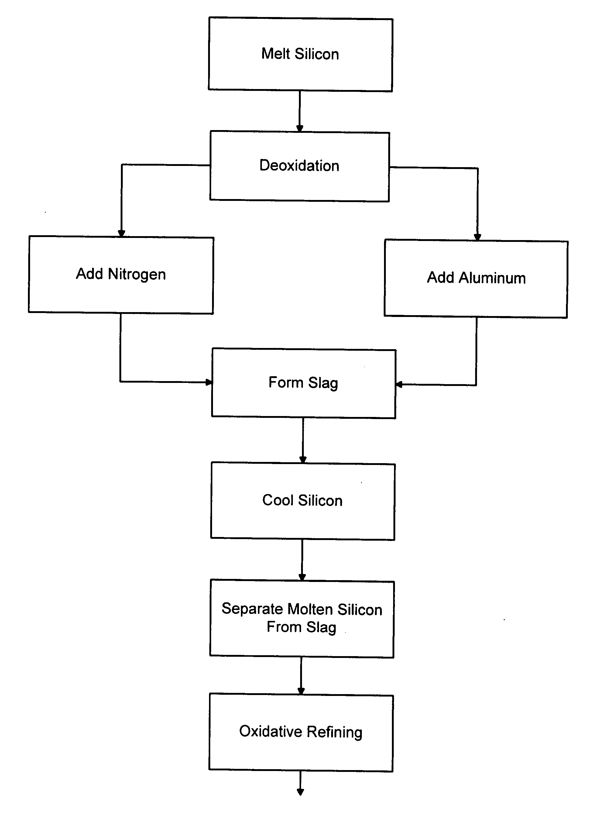
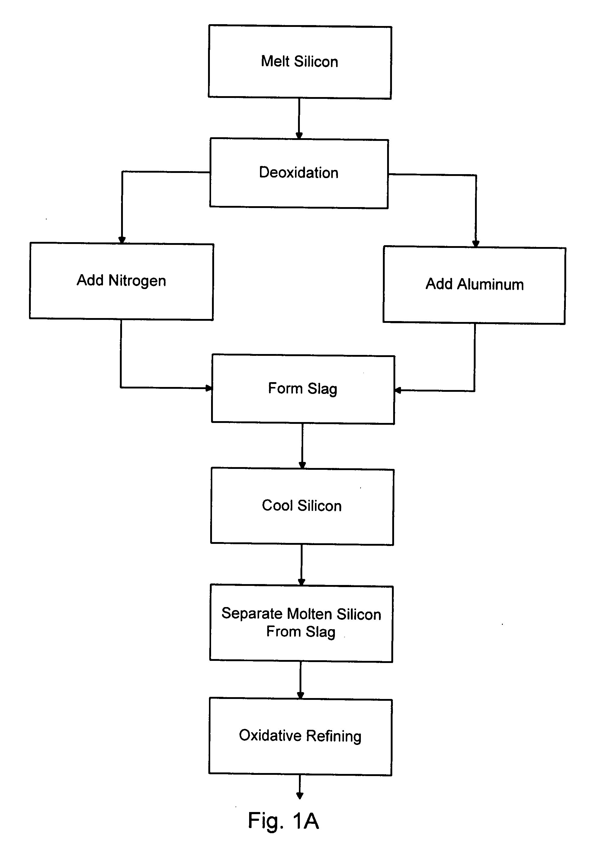
[0115] Example 1 contains a description of a typical process according to the invention which uses a slag and two vessels for deoxidation, nitriding and refining for boron and phosphorus, oxidative refining and SiC settling.

[0116] 1. Metallurgical-grade silicon is charged to the cold crucible in the vacuum chamber. Any combination of Al2O3, CaO, MgO, Al, Ca, or Mg is included in the charge to achieve the desired level of

[0117] a. Al dissolved in the silicon for phosphorus refining.

[0118] b. Al dissolved in the silicon for AlN formation during and after nitriding. AlN dissolves in the slag.

[0119] c. Al, Ca, and Mg dissolved in the silicon to maintain a highly reducing condition during boron and phosphorus refining.

[0120] 2. The chamber is sealed, then evacuated with a mechanical pump to 0.01 bar, and then back filled with purified N2 to a pressure of 1 bar or higher. This process may be repeated several times to effectively remove any residual air remaining in the chamber. The N...

example 2

[0140] Example 2 contains a description of a typical process according to the invention using a solid discard phase. Deoxidation and nitriding are the same as described in Example 1 with some slight modifications.

[0141] Refining for boron and phosphorus takes place in a separate vessel. The melt is cooled to between 1700 K and 1880 K and then passed through a bed of particulate consisting of the βss (solid discard phase) to remove boron and phosphorus. The particulate is prepared in advance and is used in a near continuous process after which the particulate is removed and replaced with new particulate. The solid phase consists of a solid solution formed from Si3N4, Al2O3, AlN, MgO, and CaO. The solids are pieces from 2 mm to 10 mm in diameter. The bed is structured, with respect to composition, by having strata so as to remove boron and phosphorus separately, but with the optimum composition for refining of the silicon with respect to the bed material, so as to achieve the greates...


PUM

PropertyMeasurementUnit
temperatureaaaaaaaaaa

Abstract

Nitrogen and aluminum and fluxing agents (Al2O3, SiO2, CaO and MgO) are added to molten silicon to create an oxy-nitride slag that acts as a sink for dissolved boron and phosphorus. The nitrogen can be added by bubbling nitrogen gas through the molten silicon; the aluminum can be added as aluminum metal or as Al2O3. Normally, the silicon must initially be deoxidized to allow the boron and phosphorus refining reactions to occur. The process may be followed by oxidative refining, SiC settling, the Silgrain process and directional solidification to remove other impurities and produce silicon suitable for use in solar cells. In an alternative version of the process, the molten silicon is passed through a particulate bed formed of a nitrogen-containing compound and an aluminum-containing compound.

Description

[0001] This application claims the priority of provisional Patent Application No. 60 / 794,695, filed Apr. 25, 2006, which is incorporated herein by reference in its entirety.FIELD OF THE INVENTION [0002] This invention relates to processes for removing impurities from silicon and, in particular, to a process for removing boron and phosphorus from metallurgical-grade silicon to produce silicon that can be used in the manufacture of solar cells. BACKGROUND OF THE INVENTION [0003] Silicon is a primary component of most solar cells manufactured today. The essential photovoltaic mechanism for converting solar energy to electrical energy relies on a PN junction that is formed in a silicon wafer. The PN junction may be formed by implanting a P-type impurity into an N-type silicon, or vice-versa. [0004] The solar cell industry has traditionally relied on silicon discarded by the electronics industry as a material source. This has significantly increased the cost of manufacturing a solar cell...

Claims


Application Information

Patent Timeline
Patent Type & Authority Applications(United States)
IPC IPC(8): C22B9/10
CPCC01B33/037C01B31/36
Inventor LYNCH, DAVID C.OYE, HARALD A.
Owner THE ARIZONA BOARD OF REGENTS ON BEHALF OF THE UNIV OF ARIZONA
Why Eureka
Try Eureka