Flow Distribution Channels To Control Flow in Process Channels

Inactive Publication Date: 2007-10-25
VELOCYS CORPORATION
View PDF43 Cites 63 Cited by
  • Summary
  • Abstract
  • Description
  • Claims
  • Application Information

AI Technical Summary

Benefits of technology

[0019] The inventive features can also serve to reduce the volume in the headers and or footers of a system. By this manner they serve to reduce the dead volume for applications that require fast transient response such as adsorption or others that are required to respond to transient changes in input parameters in a fast man

Problems solved by technology

Controlling flow from a manifold or manifolds into these parallel process microchannels has been a major challenge of scaling up microcha

Method used


Image

  • Flow Distribution Channels To Control Flow in Process Channels
  • Flow Distribution Channels To Control Flow in Process Channels
  • Flow Distribution Channels To Control Flow in Process Channels

Examples


Example

EXAMPLE 1

Flow Distribution With Flow Distribution Features

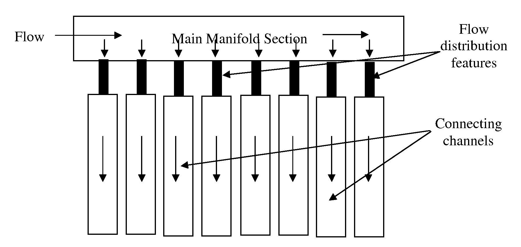
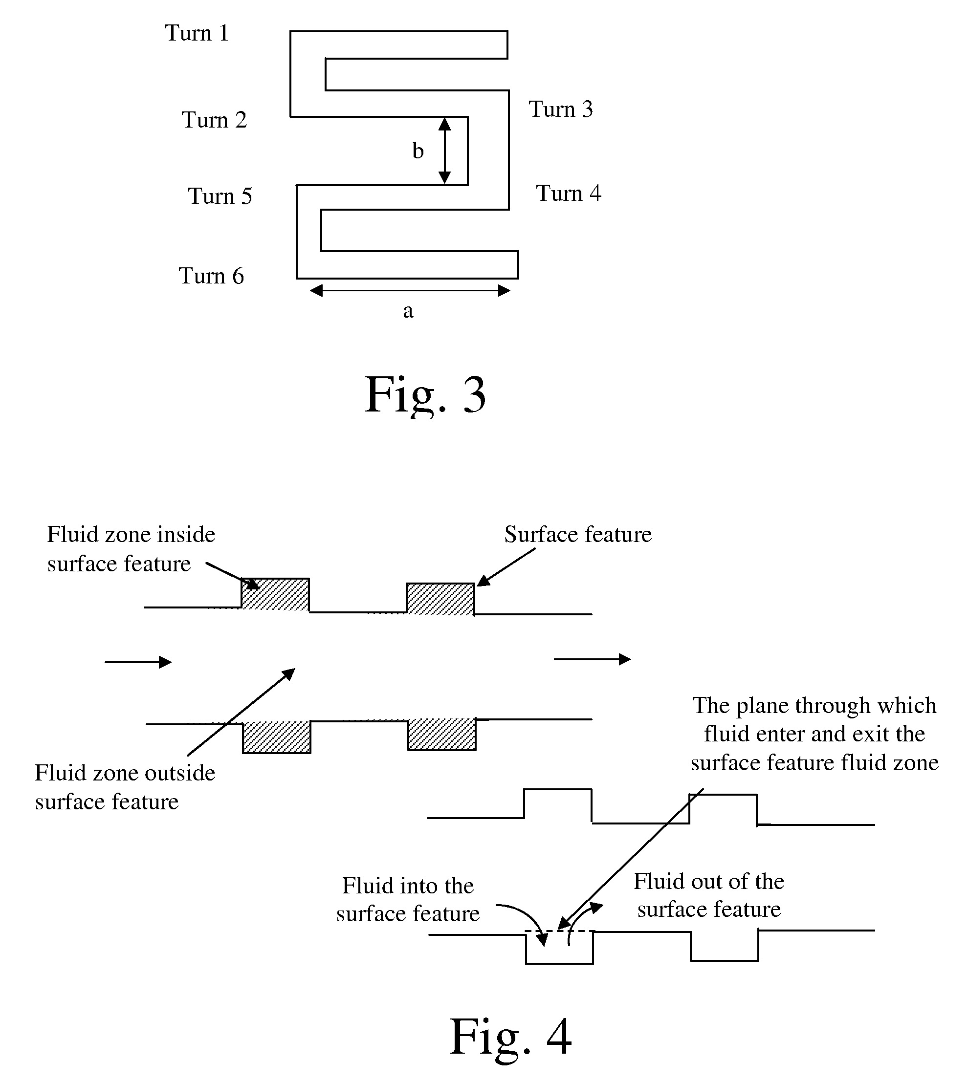
[0092] A case study was done to see the improvement in the flow distribution using flow distribution features. The general schematic of the device is shown in FIG. 5 but with a bottom manifold. The top and bottom main manifold sections were 12.7 mm×2.54 mm in cross-section. The connecting channels were 5.08 mm×0.76 mm in dimensions. The length of connecting channels was 127 mm. The connecting channels were separated by 0.508 mm wall. The number of connecting channels was 19. FIG. 4 shows the dimensions of the flow distribution features. The flow distribution features were in serpentine shape. The cross-section of the flow distribution channel was 0.76 mm×0.38 mm. The manifold, flow distribution channels and connecting (process) channels were in a common plane.

[0093] The fluid used was ethylene at 230 psig and −30° C. The total flow rate entering the main manifold section was 0.487 kg / hr. The performance of flow distributio...

Example

EXAMPLE 2

Flow Distribution Features Provide Uniform Flow Distribution Over a Wide Range of Turn-up and Turn-down Flow Rates From Nominal

[0098] A geometry the same as in Example 1 was used to show that the flow distribution features provide relatively uniform flow distribution for turn-up and turn-down flow rates. The flow distribution results were compared to the flow distribution obtained in the same geometry but without flow distribution features. The fluid, temperature and outlet pressure conditions were kept for both the cases: with flow distribution feature and without flow distribution features. The fluid used was ethylene at 230 psig and −30° C. The nominal total flow rate entering the main manifold section was 0.487 kg / hr.

[0099]FIG. 29 shows the quality factors with different turn-up and turn-down factors from nominal flow rates for design with flow distribution features and without flow distribution features. A turn-up / turn-down ratio of 0.8 means 80% of nominal flow rat...

Example

EXAMPLE 3

Flow Distribution for Emulsion

[0101] An emulsion is formed by mixing continuous phase liquid with dispersed phase liquid through a porous medium. It is desired for manufacturing that the porous medium through which continuous and dispersed phases are mixed should be replaceable preferably with mixing of the continuous and dispersed phases while flowing in cross-flow direction. However depending upon the requirement, the continuous and dispersed phases can be mixed while flowing co-current or counter-current to each other.

[0102] In this example, only a repeating unit was modeled to describe the performance of the device. The repeating unit has three layers stacked together. The continuous phase enters the first layer as shown in the schematic in the FIG. 9. The flow enters the inlet manifold section. The cross-section of the manifold was 25.4 mm wide×5.08 mm depth. The connecting channel dimensions were 12.7 mm wide×2.03 mm depth×305 mm length. There were total 16 connect...


PUM

PropertyMeasurementUnit
Fractionaaaaaaaaaa
Fractionaaaaaaaaaa
Angleaaaaaaaaaa

Abstract

The invention describes features that can be used to control flow to an array of microchannels. The invention also describes methods in which a process stream is distributed to plural microchannels.

Description

RELATED APPLICATIONS [0001] In accordance with 35 U.S.C. sect. 119(e), this application claims priority to provisional patent application Ser. No. 60 / 745,614 filed 25 Apr. 2006.GOVERNMENT RIGHTS [0002] This invention was made with Government support under contract DE-FE36-04GO14271 awarded by the United States Department of Energy. The government has certain rights in the invention.FIELD OF THE INVENTION [0003] This invention relates to flow control in microchannel devices. INTRODUCTION [0004] Many microchannel devices contain numerous planar, parallel process microchannels. Controlling flow from a manifold or manifolds into these parallel process microchannels has been a major challenge of scaling up microchannel devices. Examples of techniques to control flow (and typically to equalize flow) in parallel process microchannels have been described by Fitzgerald et al. in U.S. Published Patent Application Nos. 2005 / 0087767 and 2006 / 0275185, both of which applications are incorporated ...

Claims


Application Information

Patent Timeline
IPC IPC(8): F16L41/00
CPCB01F3/0807B01F13/0074B01F5/0646B01F5/0647B01F5/0655B01F13/0059B01J19/0093B01J2219/00783B01J2219/00835B01J2219/0086B01J2219/00869B01J2219/00873B01J2219/00889B01J2219/00891F28F9/0275F28F2260/02B01F5/0475Y10T137/85938Y10T137/6579Y10T137/0318Y10T137/0329Y10T137/87652Y10T137/87571B01F23/41B01F25/3142B01F25/4338B01F25/4331B01F25/433B01F33/30F28D1/0341F28F1/022F28D1/0316F28F3/04B01F33/305B01F33/3017
Inventor TONKOVICH, ANNA LEEARORA, RAVIKILANOWSKI, DAVID
Owner VELOCYS CORPORATION
Why Eureka
Try Eureka