System for optimizing oxygen in a boiler

Active Publication Date: 2007-10-25
GENERAL ELECTRIC CO
View PDF24 Cites 85 Cited by
  • Summary
  • Abstract
  • Description
  • Claims
  • Application Information

AI Technical Summary

Benefits of technology

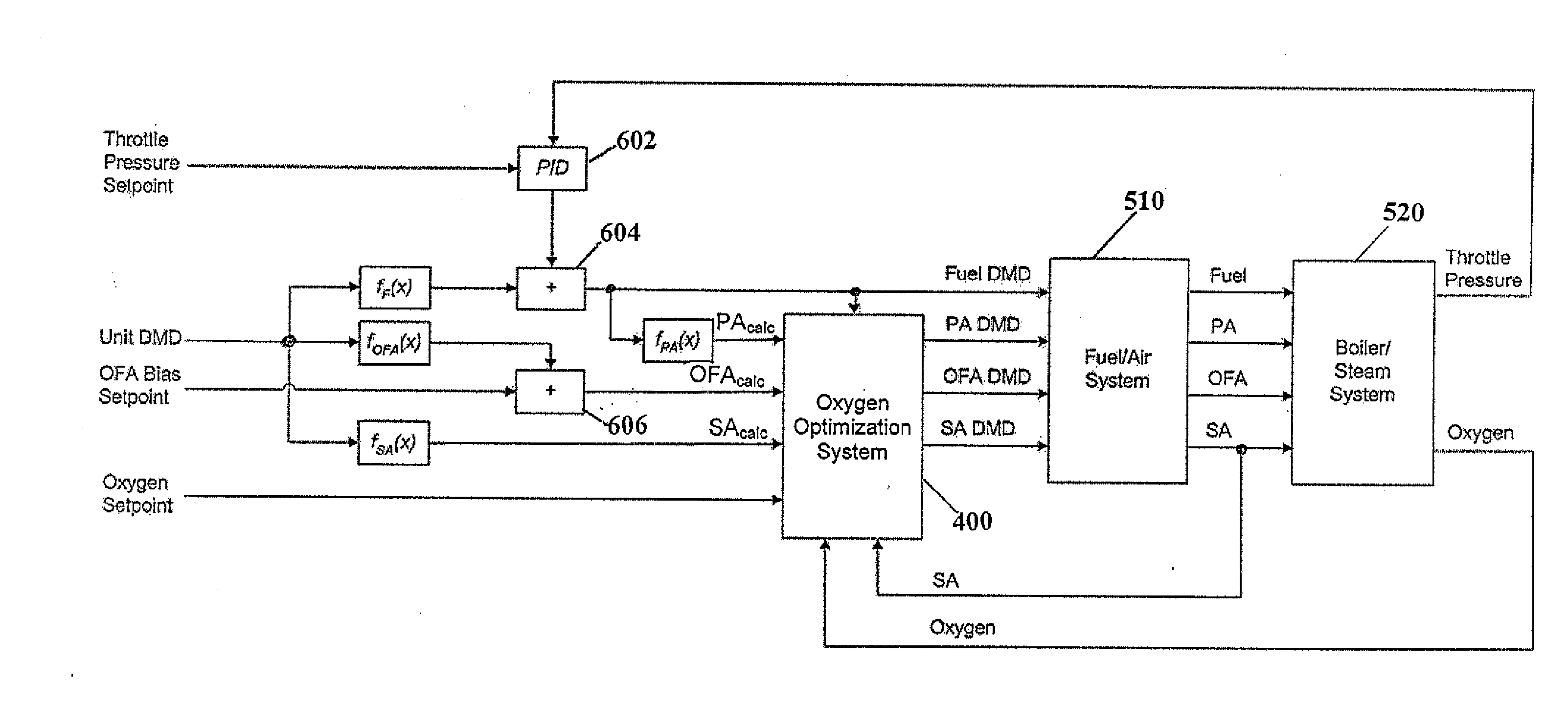
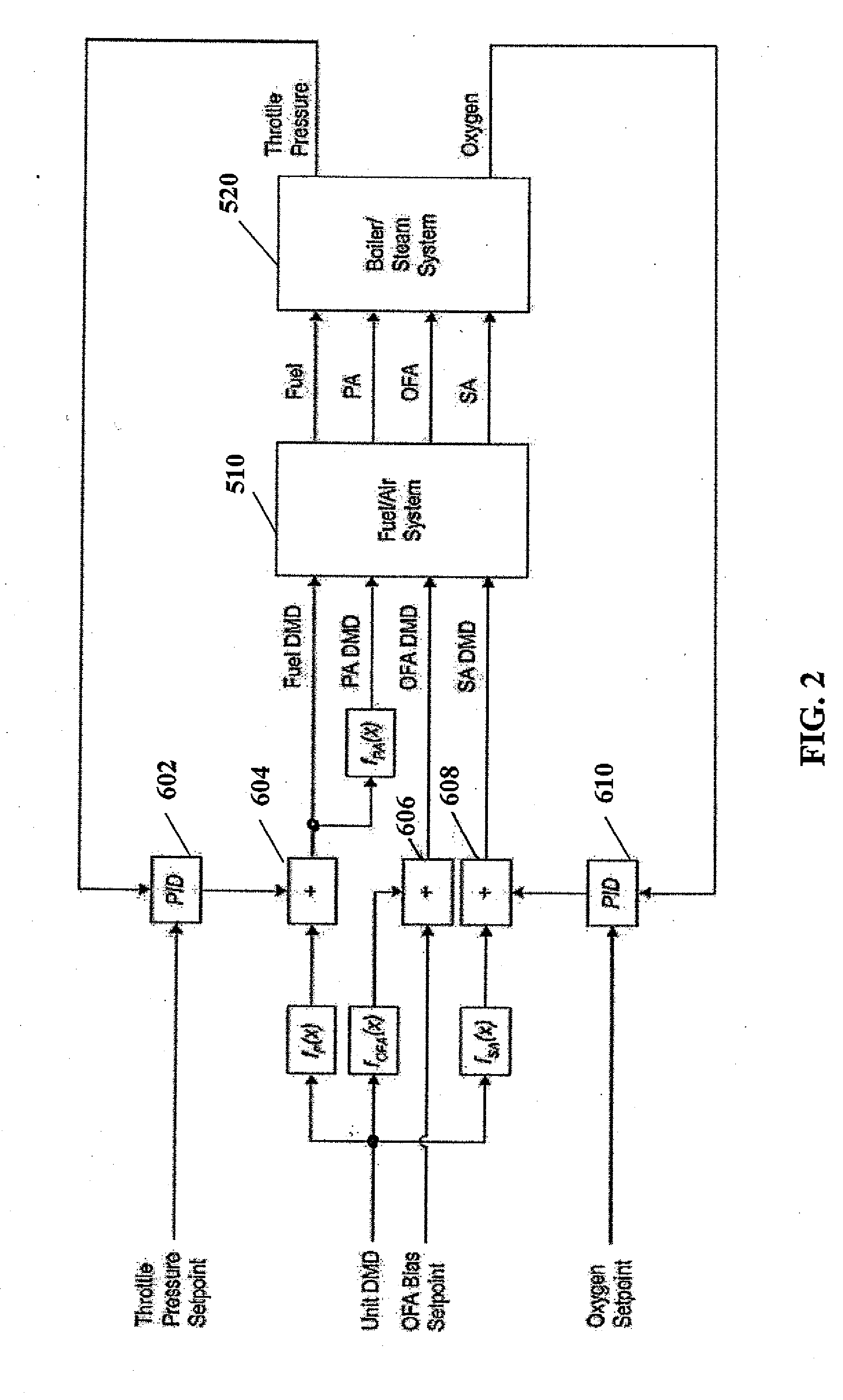
[0023] An advantage of the present invention is the provision of a control system including an oxygen optimization system for optimizing oxygen in a power generating unit.
[0024] Another advantage of the present invention is the provision of a control system including an oxygen optimization system that controls air flow to the boiler.
[0025] Still another advantage of the present invention is the provision of a control system including

Problems solved by technology

Although the DCS is typically capable of providing adequate regulatory control of the power generating unit, there are a significant number of situations where a DCS based control scheme is not sufficient for maintaining the appropriate operating conditions in the boiler.
For example, large variations in the heat content of the fuel and inaccurate oxygen sensor readings can lead to flame extinction of burners using typical DCS control schemes.
If large fuel variations or inaccurate oxygen readings are known to exist, operators are required to either manually control the boiler or use artificially high levels of oxygen to prevent flame extinction.
Variations in heat content of the fuel can lead to flame extinction or flame instability of burners due to inadequate air flow.
At some point, if the heat content falls too low, flame extinction of the burner becomes highly probable due to the lack of sufficient secondary air.
Because it is difficult and expensive to instantaneously determine the heat content of the fuel using sensors, it is difficult to create an algorithm to recognize this situation in the DCS using commonly available logic and control schemes.
Therefore, current DCS logic and control schemes can lead to the high probability of flame extinction if the heat content of the

Method used


Image

  • System for optimizing oxygen in a boiler
  • System for optimizing oxygen in a boiler
  • System for optimizing oxygen in a boiler

Examples


Example

[0038] It should be understood that the various systems described in the illustrated embodiments of the present invention may take the form of computer hardware, computer software, or combinations thereof. The computer hardware may take the form of a conventional computer system including a processor, data storage devices, input devices (e.g., keyboard, mouse, touch screen and the like), and output devices (e.g., display devices such as monitors and printers), or be embodied as part of another computer system.

[0039] Furthermore, the specific inputs and outputs of each model disclosed herein are shown solely for the purpose of illustrating an embodiment of the present invention. In this regard, it is contemplated that the specific model inputs and outputs may vary according to the requirements of the model and the desired predicted values that are being determined by the model.

[0040] The present invention is described herein with reference to power generating units for the generati...


PUM


Abstract

A method and apparatus for optimizing air flow to a boiler of a power generating unit using advanced optimization, modeling, and control techniques. Air flow is optimized to maintain flame stability, minimize air pollution emissions, and improve efficiency.

Description

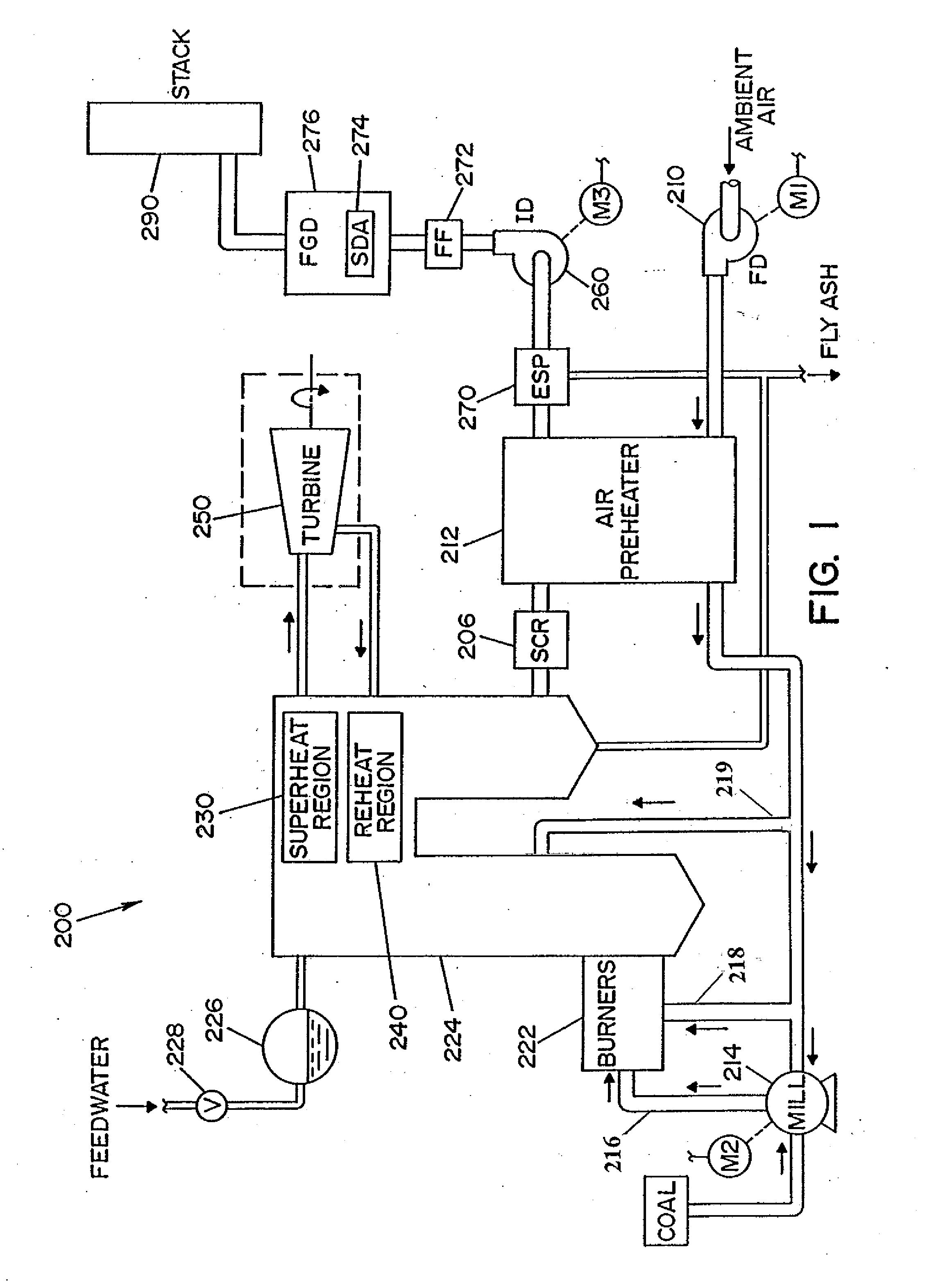
FIELD OF THE INVENTION [0001] The present invention relates generally to the operation of a power generating unit, and more particularly to a method and apparatus for optimizing the air flow to a boiler of a power generating unit using advanced optimization, modeling, and control techniques to maintain flame stability, minimize air pollution emissions, and improve efficiency. BACKGROUND OF THE INVENTION [0002] In a conventional fossil fuel-fired (e.g., coal-fired) power generating unit, a fossil fuel / air mixture is ignited in a boiler. Large volumes of water are pumped through tubes inside the boiler, and the intense heat from the burning fuel turns the water in the boiler tubes into high-pressure steam. In an electric power generating application, the high-pressure steam from the boiler passes into a turbine comprised of a plurality of turbine blades. Once the steam hits the turbine blades, it causes the turbine to spin rapidly. The spinning turbine causes a shaft to turn inside a ...

Claims


Application Information

Patent Timeline
IPC IPC(8): G05B21/00
CPCG05B13/048
Inventor JIA, JIANHUPICHE, STEPHENBEAVER, W. HARDEY
Owner GENERAL ELECTRIC CO
Why Eureka
Try Eureka