Device for Removing Particulate, Various Acids, and Other Contaminants from Industrial Gases

a technology of industrial gases and devices, applied in separation processes, auxillary pretreatment, filtration separation, etc., can solve the problems of increasing cancer risk, negative effects on surrounding vegetation, and health related issues, and achieve the effect of reducing the emission of nitrous oxides and reducing the final exhaust gas volum

Inactive Publication Date: 2007-11-01
ARTEC 1
View PDF6 Cites 61 Cited by
  • Summary
  • Abstract
  • Description
  • Claims
  • Application Information

AI Technical Summary

Benefits of technology

[0009] The present invention pertains to a device for removing particulates, acids, heavy metals, and other contaminants from production sources such as internal combustion engines, boilers, incinerators, pyrolysis systems or waste gasifiers, dryers, paint booths, or other such sources of air pollution. For example, the present invention may assist in reducing the emission of nitrous oxides from waste gasification systems, such as that described in U.S. patent application Ser. Nos. 10/632,043 and 10/882,133, both of which are incorporated herein by reference in their entirety. The invent...

Problems solved by technology

Industrial air emissions are often cited as a source of various environmental problems, such as ozone layer depletion, global warming, and acid rain, not to mention health related issues for those individuals working or residing in affected areas.
For example, incineration of organic materials often results in the formation of carbon dioxide and nitrous oxides, which are implicated with, among other things, the formation of volatile organic compounds that contribute to smog problems in urban areas.
Such pollution is known to lead to various health related issues, such as pulmonary disease and increased cancer risks, as well as having negative effects on surrounding vegetation.
As public sentiment and governments continue to pursue enactme...

Method used


Image

  • Device for Removing Particulate, Various Acids, and Other Contaminants from Industrial Gases
  • Device for Removing Particulate, Various Acids, and Other Contaminants from Industrial Gases
  • Device for Removing Particulate, Various Acids, and Other Contaminants from Industrial Gases

Examples


Embodiment Construction

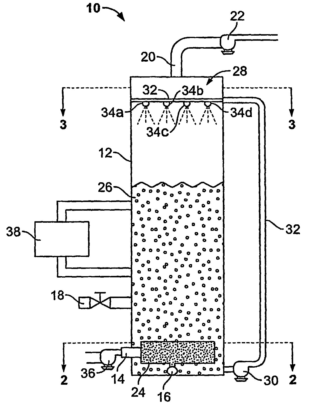
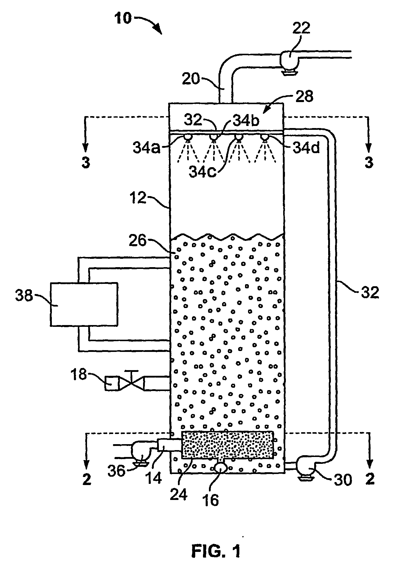
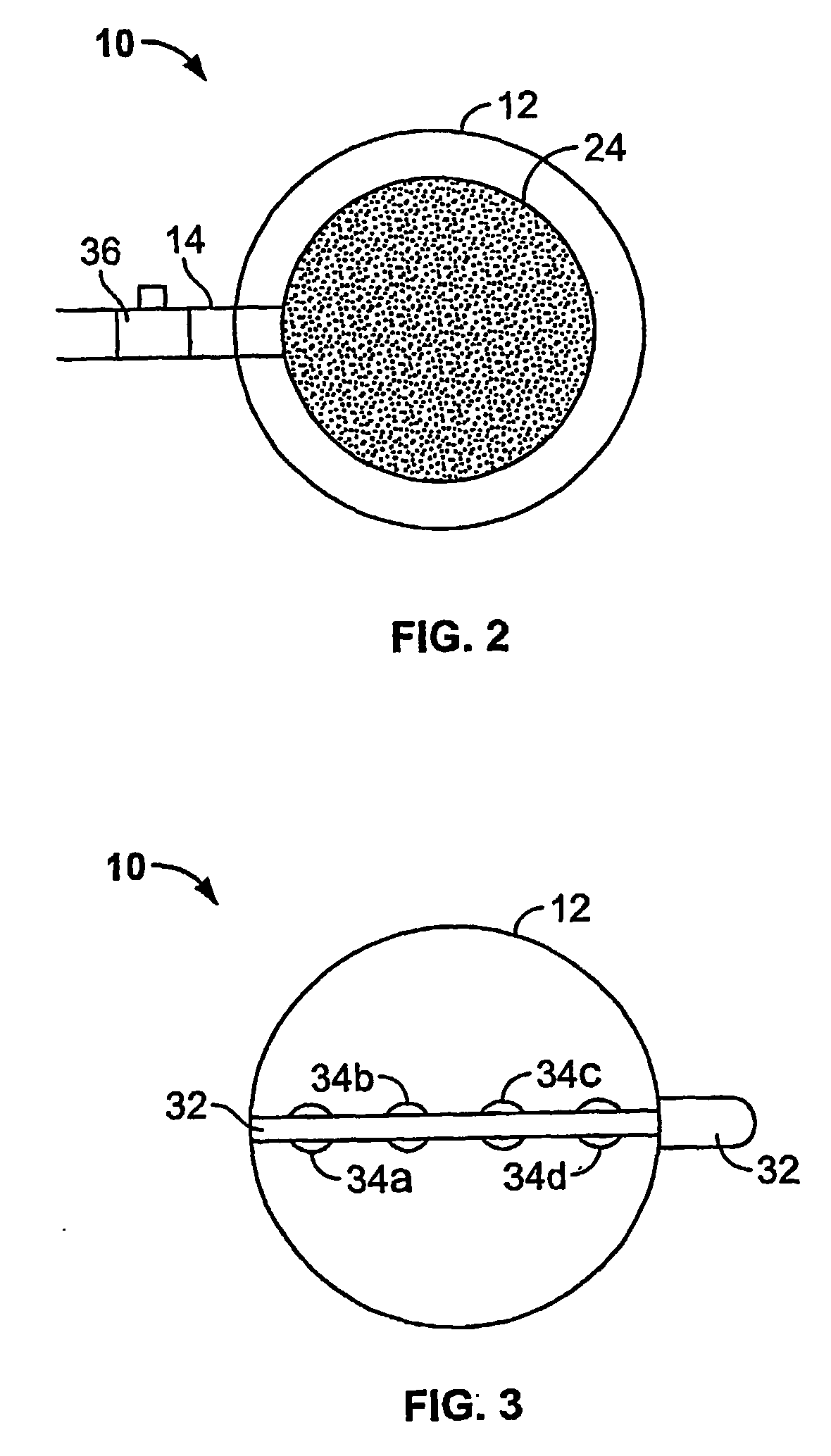
[0022]FIG. 1 illustrates a side elevation view of a columnar vessel 10 configured to reduce or remove the presence of contaminants in production source exhaust gases in accordance with the illustrated embodiment of the present invention. The columnar vessel 10 includes a tank 12, an inlet port 14, an exhaust port 20, a diffuser 24, solution 26, and a mist assembly 28. The number and the size of columnar vessels 10 required may be determined by the particular needs of the associated production source(s).

[0023] The tank 12 includes an interior portion, a lower end, and an upper end. As shown in FIG. 1, the tank 12 may be vertical and may be constructed from a variety of materials, including metallic materials or materials that offer some resistance to acidic or caustic corrosion, such as fiberglass or plastic. The tank 12 may be sized to accommodate the throughput of exhaust gas from the production source at a flow rate which provides adequate retention time of the exhaust gas in the...


PUM

PropertyMeasurementUnit
Timeaaaaaaaaaa
Proximity effectaaaaaaaaaa

Abstract

Exhaust gases enter the tank of a columnar vessel (12) and are subsequently forced through a diffuser (24) that is at least partially immersed in a column of solution.

Description

RELATED APPLICATIONS [0001] This application claims the benefit of U.S. Provisional Application No. 60 / 518,076, filed Nov. 7, 2003, which is incorporated herein by reference in its entirety.BACKGROUND OF THE INVENTION [0002] Industrial air emissions are often cited as a source of various environmental problems, such as ozone layer depletion, global warming, and acid rain, not to mention health related issues for those individuals working or residing in affected areas. For example, incineration of organic materials often results in the formation of carbon dioxide and nitrous oxides, which are implicated with, among other things, the formation of volatile organic compounds that contribute to smog problems in urban areas. Such pollution is known to lead to various health related issues, such as pulmonary disease and increased cancer risks, as well as having negative effects on surrounding vegetation. As public sentiment and governments continue to pursue enactment of stricter emission ...

Claims


Application Information

Patent Timeline
IPC IPC(8): B01D47/02B01D47/12B01D53/14B01D53/18
CPCB01D47/06B01D47/12B01D47/021B01D53/18F01N13/004B01D53/1456
Inventor POPE, G. MICHAELGREEN, JERRY
Owner ARTEC 1
Why Eureka
Try Eureka