Worm reduction gear and electric power steering apparatus

a technology of electric steering apparatus and worm reduction gear, which is applied in the direction of gearing details, gearing, transportation and packaging, etc., can solve the problems of unavoidable backlash, increase in dimensional errors, and increase in backlash, so as to suppress the generation of grating teeth hitting noise at these meshing parts, the effect of low cos

Active Publication Date: 2007-11-01
NSK LTD +1
View PDF16 Cites 28 Cited by
  • Summary
  • Abstract
  • Description
  • Claims
  • Application Information

AI Technical Summary

Benefits of technology

[0015] In view of the above problems, the present invention has been invented so as to suppress the generation of the grating teeth hitting noise at the meshing parts between the worm wheel and the worm shaft, with a low cost construction.
[0017] In the case of the worm reduction gear and the electric power steering apparatus incorporating this worm reduction gear of the present invention, as described above, the elastic body applies an elastic force to the worm shaft in a direction towards the worm wheel. Therefore, a pre-load can be applied to the meshing parts between the worm wheel and the worm shaft with a low cost construction, and the generation of the grating teeth hitting noise at these meshing parts can be suppressed.

Problems solved by technology

However, in this worm reduction gear, there is unavoidable backlash.
This backlash becomes larger with increase in dimensional errors and assembly errors of the worm shaft, the worm wheel, and the bearings etc. for supporting these members, being the components of the worm reduction gear.
Furthermore, if a large backlash exists, the teeth surfaces of the worm wheel and the worm strongly collide with each other, with the likelihood of generation of a grating teeth hitting noise.
For example, if the vibrational load due to roughness of the road is transmitted from the vehicle wheel side to the steering shaft 2, then due to the presence of this backlash, a grating teeth hitting noise is generated.
Moreover, due to the collision of the teeth surfaces of the worm wheel and the worm, the operating feeling when steering the steering wheel is impaired.
However, if backlash is reduced in this way, management of dimensional accuracy, and the assembly operation becomes troublesome, and leads to increased cost.
Therefore the friction between the teeth surfaces of the worm wheel and the worm is increased so that backlash is more likely to occur.
If the teeth hitting noise based on this backlash leaks into the cabin space of the vehicle, it is annoying to the occupants.

Method used


Image

  • Worm reduction gear and electric power steering apparatus
  • Worm reduction gear and electric power steering apparatus
  • Worm reduction gear and electric power steering apparatus

Examples


example 1

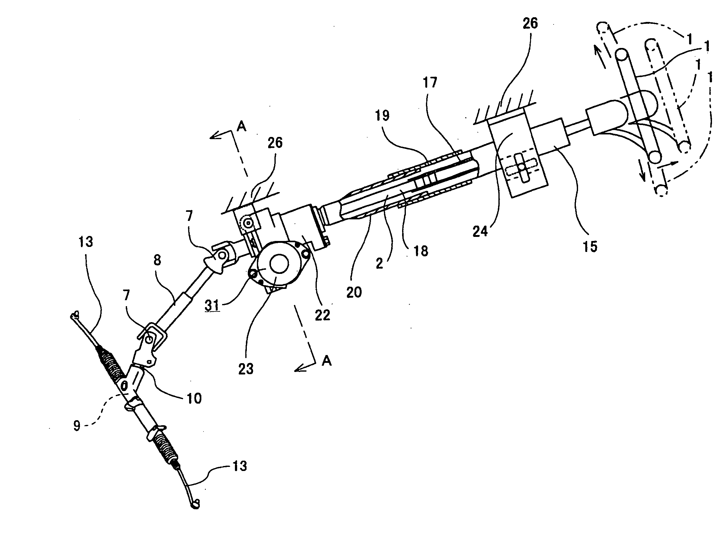
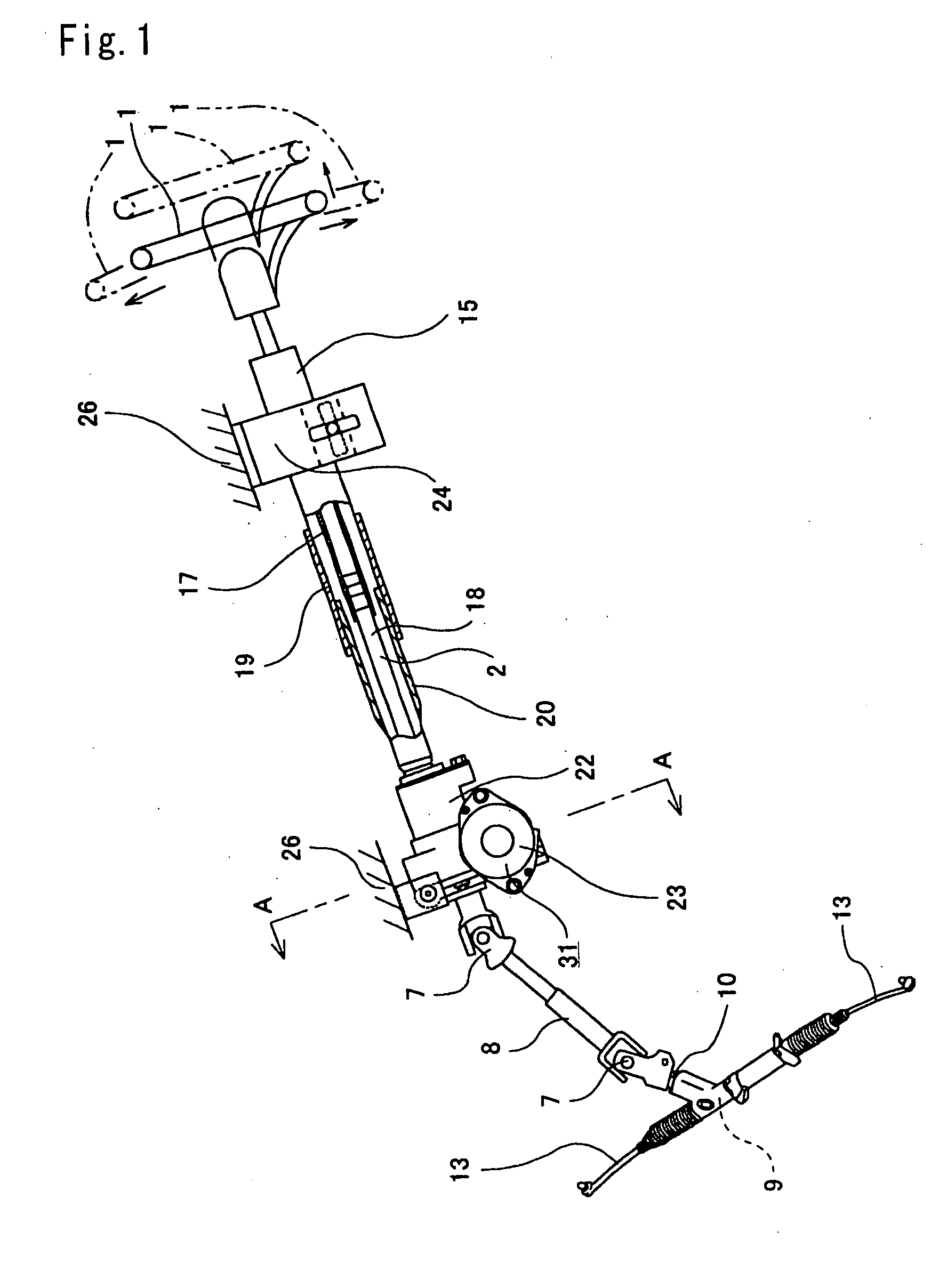
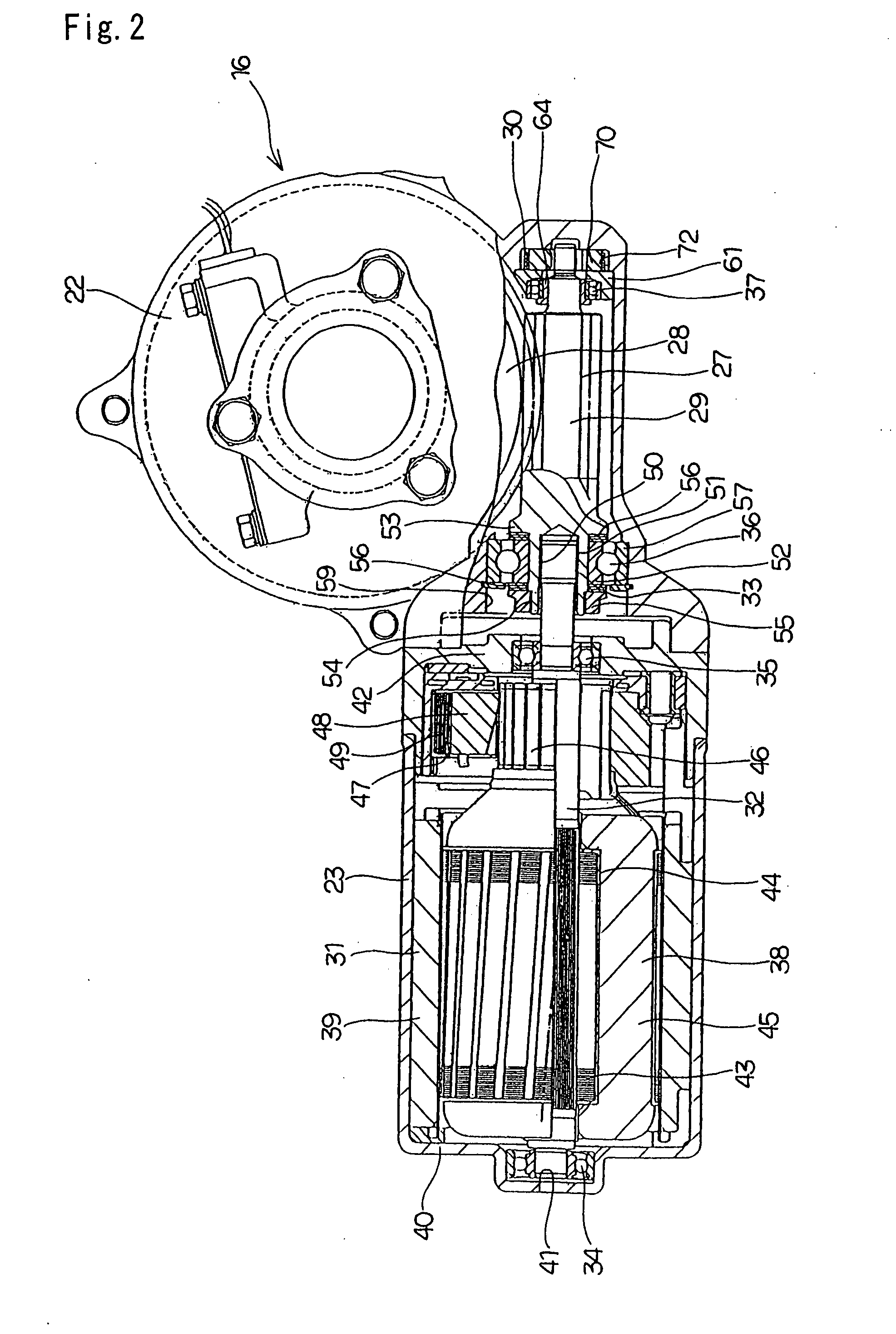
[0151] FIGS. 1 to 9 show a first example of the present invention. The electric power steering apparatus of this example comprises: a steering shaft 2 being an assist shaft which is secured at a rear end portion to a steering wheel 1; a steering column 15 through which the steering shaft 2 passes freely; a worm reduction gear 16 for applying a supplementary torque to the steering shaft 2; a pinion 11 (refer to FIG. 46) provided on the front end of the steering shaft 2; a rack 12 (refer to FIG. 46) which is meshed with the pinion 11 or with a member supported on the pinion 11; a torque sensor 3 (refer to FIG. 46); an electric motor 31; and a controller 6 (refer to FIG. 46).

[0152] The steering shaft 2 is made by assembling an outer shaft 17 and an inner shaft 18 by a spline engaging section so as to freely transmit a rotation force and enable axial movement. Moreover, in the case of this example, the front end portion of the outer shaft 17 and the rear end portion of the inner shaft ...

example 2

[0175] Next, FIG. 10 shows a second example of the present invention. In the case of this example, the position of contact portions 94a between an inner peripheral face of a through hole 71a provided in a pre-load pad 70, and an outer peripheral face of a small diameter portion 68 provided on the tip end portion of a worm shaft 29 is different to the case of the aforementioned first example. That is to say, in the case of this example, the contact portions 94a between the worm shaft 29 and the pre-load pad 70 are provided at three locations evenly spaced around the circumferential direction, being symmetric in relation to the direction of arrow (a) in FIG. 10 being the direction of action of the reaction force in a direction perpendicular to the central axis of the worm shaft 29, for a predetermined rotation direction of the worm wheel 28 where the reaction force applied from the worm wheel 28 (refer to FIGS. 4 and 5) to the worm shaft 29 tends to be large.

[0176] In the case of thi...

example 3

[0177] Next, FIGS. 11 and 12 show a third example of the present invention. In the case of this example, a pre-load pad 70a is constructed by assembling together two different elements 110a and100b. These two elements 110a and 110b have the discontinuous portion 90 of the pre-load pad 70 which constitutes the construction of the first example shown in FIGS. 1 to 9, provided centrally in the widthwise direction, and have a shape obtained by cutting the pre-load pad 70 at a position on the opposite side to the discontinuous portion 90 in relation to the central axis of the through hole 71 (refer to FIG. 7). That is to say, each of the elements 110a and 110b are respectively provided with concave portions 111 of an approximately half cylindrical shape in an intermediate portion in the length direction (the up and down direction in FIGS. 11 and 12) of one side face facing each other, and planar portions 112a and 112b on portions at both ends in the length direction. Furthermore, on the ...


PUM


Abstract

A torsion coil spring 30 applies an elastic force to a worm shaft 29 in a direction towards a worm wheel, via a pre-load pad 70. The pre-load pad 70 restricts displacement in relation to the widthwise direction, by one side face portion of a holder 61 fixed to a gear housing 22. Due to the elastic deformation of the pre-load pad 70 itself based on the elastic force of the torsion coil spring 30, the side face of the pre-load pad 70 is abutted against the one side face portion of the holder 61, so that a gap between the pre-load pad 70 and the one side face portion is minimized. As a result, the occurrence of a teeth fitting noise in the worm reduction gear 16 is suppressed.

Description

CROSS REFERENCE TO RELATED APPLICATIONS [0001] This application is a divisional of U.S. application Ser. No. 10 / 540,625, filed Jun. 24, 2005, which is a continuation of PCT application PCT / JP2004 / 008887, filed Jun. 24, 2004, which claims priority under 35 U.S.C. §119 to Japanese patent applications JP2003-180959, filed Jun. 25, 2003, JP2003-271418, filed Jul. 7, 2003 and JP2004-181600, filed Jun. 18, 2004, the entire disclosures of which are herein expressly incorporated by reference.TECHNICAL FIELD [0002] The worm reduction gear and electric power steering apparatus according to the present invention is assembled for example in a vehicle steering system, and is used for reducing the force necessary for a driver to operate a steering wheel, by using the output from an electric motor as auxiliary power source. Other than the electric power steering apparatus, the worm reduction gear according to the present invention, can also be used in combination with an electric linear actuator a...

Claims


Application Information

Patent Timeline
Patent Type & Authority Applications(United States)
IPC IPC(8): B62D5/04F16H1/16F16H57/021F16H57/039H02K7/08H02K7/116
CPCB62D5/0409F16H1/16F16H57/021Y10T74/19828H02K7/081H02K7/1166F16H2057/0213F16H2057/0222F16C25/083F16C2361/61F16C2380/27F16H55/24
Inventor SEGAWA, TORUCHIKARAISHI, KAZUO
Owner NSK LTD
Why Eureka
Try Eureka