
Reflection type liquid crystal display apparatus and substrate for reflection type liquid crystal display

a liquid crystal display and reflection type technology, applied in non-linear optics, static indicating devices, instruments, etc., can solve problems such as significant degradation of image quality

Inactive Publication Date: 2007-11-01
CANON KK
View PDF6 Cites 8 Cited by
  • Summary
  • Abstract
  • Description
  • Claims
  • Application Information

AI Technical Summary

Benefits of technology

[0028]The object of the present invention is to decrease cross-talk given to an end of a capacitor (a drain wiring, a capacitor electrode, and a reflective electrode) by a signal line by forming a switching element and a large capacitor in a limited pixel size, and, as the results, to provide a reflection type liquid crystal display apparatus which can obtain a high quality image.
[0033]According to the present invention, even if the pixel size is small, a large capacitance value of the capacitor can be obtained, thereby, cross-talk from the signal line to the drain wiring of the switching transistor, the capacitor electrode, and the reflective electrode, can be decreased. As the results, it is possible to provide a reflection type liquid crystal display apparatus which can obtain a good output image.

Problems solved by technology

If the potential of the electrode of the capacitor in a held state is changed, optical properties of a liquid crystal is changed, and thereby, an original image cannot be expressed, thus resulting in significant degradation of image quality.

Method used


Image

  • Reflection type liquid crystal display apparatus and substrate for reflection type liquid crystal display
  • Reflection type liquid crystal display apparatus and substrate for reflection type liquid crystal display
  • Reflection type liquid crystal display apparatus and substrate for reflection type liquid crystal display

Examples


embodiment 1

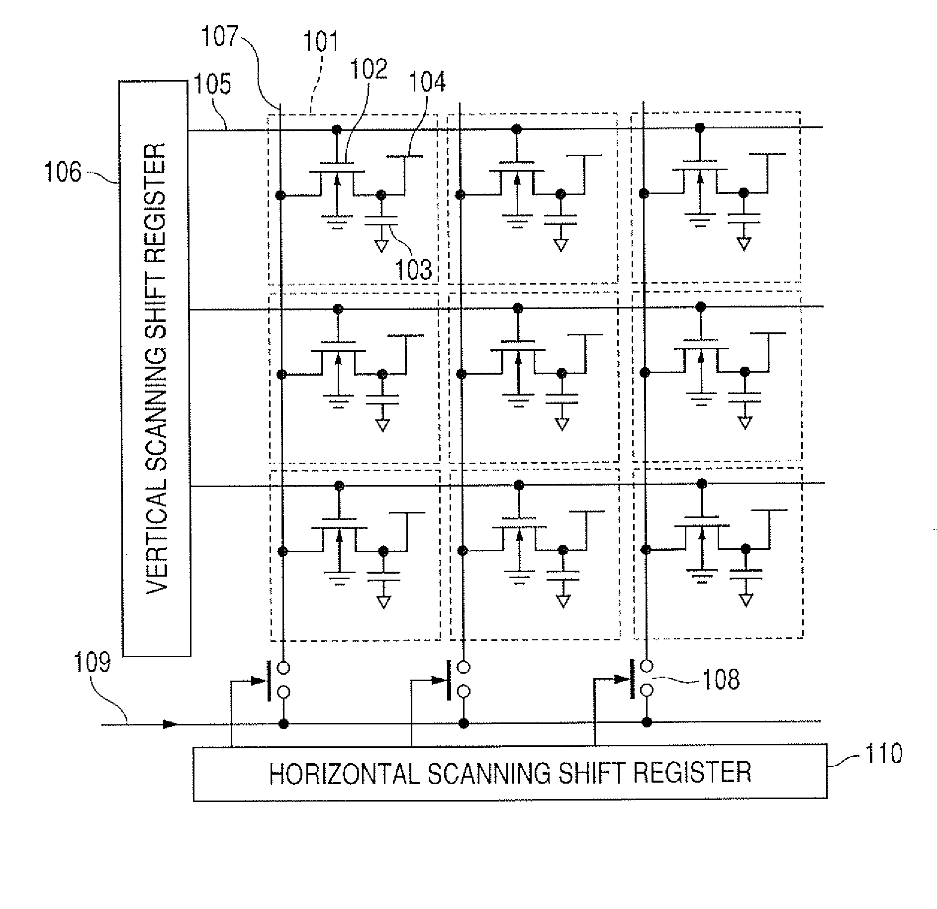
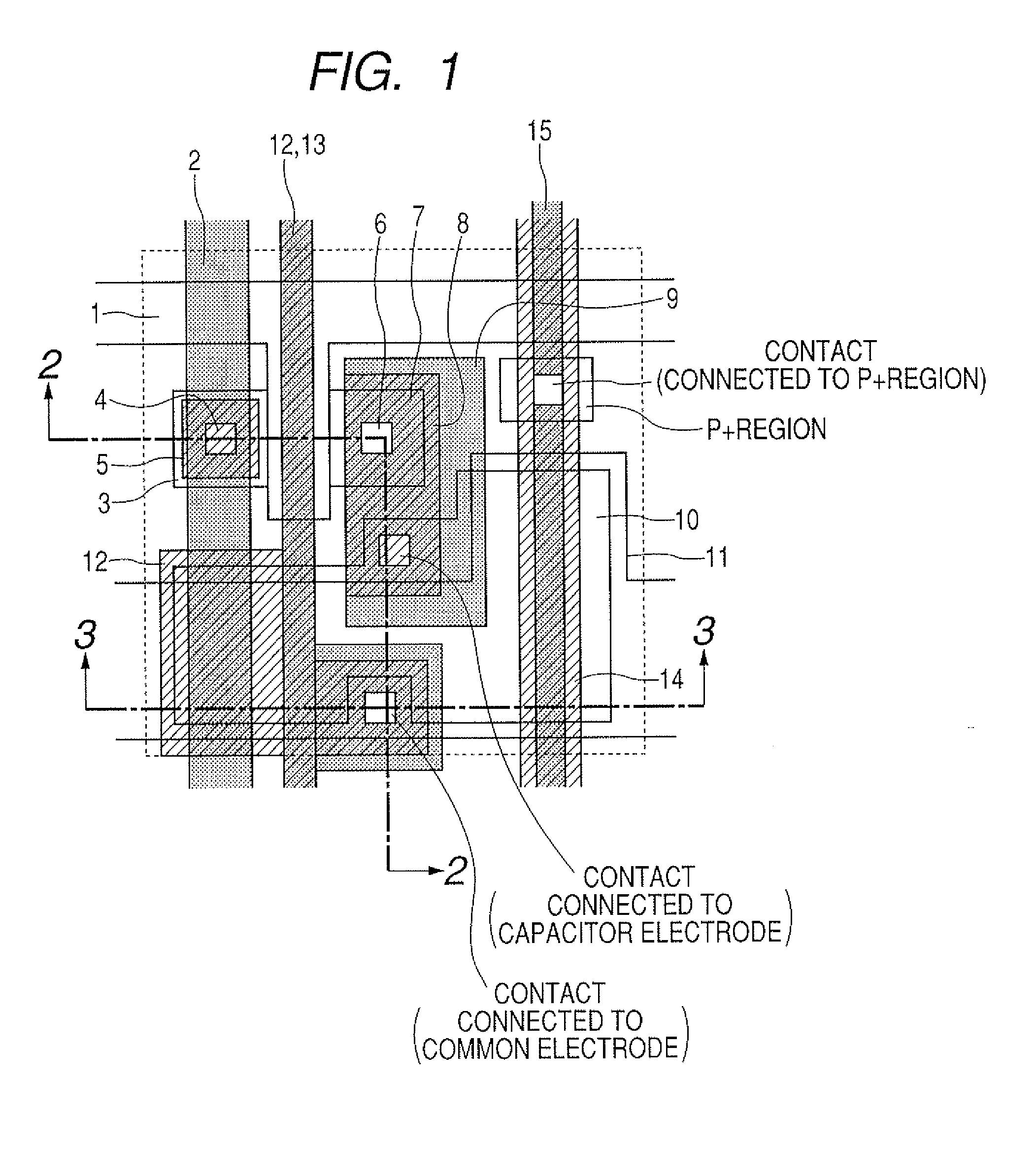
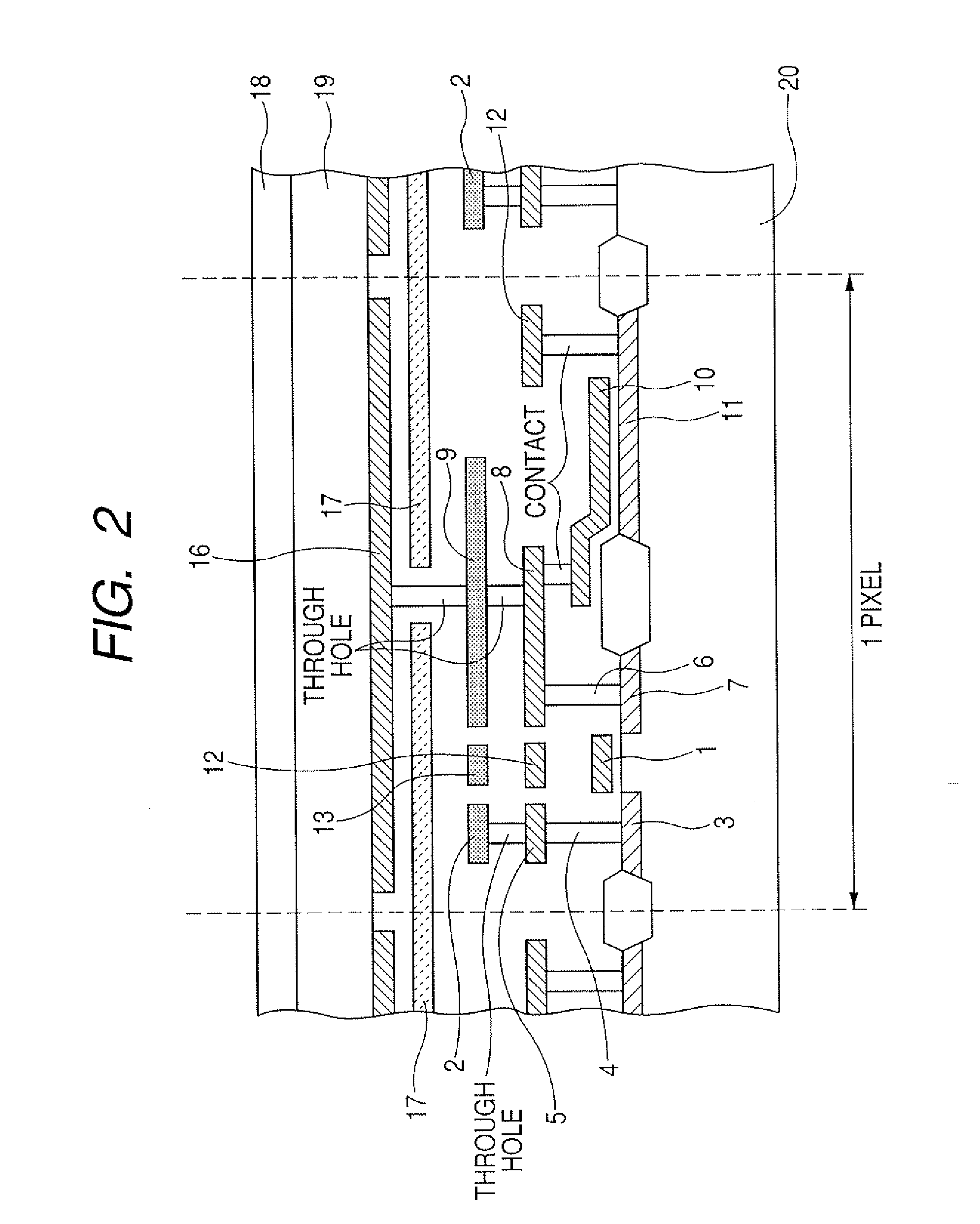
[0050]FIG. 1 is a schematic plan view of a pixel illustrating a first embodiment of the present invention, FIG. 2 is a cross-sectional view along line 2-2 in FIG. 1, and FIG. 3 is a cross-sectional view along line 3-3 in FIG. 1. FIG. 7 is a block diagram describing a drive circuit of an active matrix in a reflection type liquid crystal display apparatus of the present invention. In addition, in FIG. 1, for ease of seeing the drawing, only the side (a reflective electrode, a light shielding layer, and a through hole connected to the reflective electrode are not included) of a Si substrate (semiconductor substrate) from a light shielding layer illustrated in FIG. 2 is described. In addition, in this embodiment, a p-type Si substrate is used as a semiconductor substrate having an active matrix drive circuit, and a switching element is assumed to be a switching transistor having an NMOS transistor. Moreover, a circuit operation as a liquid crystal display apparatus, will be described wi...

embodiment 2

[0073]FIG. 4 is a schematic plan view illustrating a second embodiment of the present invention, and FIG. 5 is a cross-sectional view in along line 5-5 in FIG. 4. Moreover, FIG. 6 is a cross-sectional view in along line 6-6 in FIG. 4.

[0074]The main difference between this embodiment and the first embodiment is in that an electrode having an N+ type diffusion layer, which is the first electrode of the capacitor, is brought into contact to the drain region of a switching transistor, and connected to the drain wiring and the reflective electrode, and, in that the common electrode, which is the second electrode forming the capacitor, is formed with polysilicon and connected to a shield line. In this embodiment, a layer corresponding to the second metal layer in Embodiment 1 is not necessary.

[0075]Hereinafter, the pixel layout and the cross-sectional structure illustrated in FIG. 4 will be described.

[0076]A part of a gate line 1 formed with polysilicon is branched and acts the gate of a ...

embodiment 3

[0085]Now, with reference to FIG. 8, a liquid crystal projector system using a reflection type liquid crystal display apparatus which uses an active matrix substrate of the present invention, will be described. In FIG. 8, an example of an optical system for a liquid crystal projector is illustrated. A lump 1101, a reflector 1102, a rod integrator 1103, a collimater lens 1104, a polarization converting system 1105, a relay lens 1106, and a dichroic mirror 1107 are illustrated. Moreover, a polarization beam splitter 1108, a cross-prism 1109, a reflection type liquid crystal panel using an active matrix substrate of the present invention 1110, a projection lens 1111, and a total reflection mirror 1112 are illustrated.

[0086]Light flux emitted from the lamp 1101 is reflected by the reflector 1102, and focused in the entrance of the integrator 1103. The reflector 1103 is an elliptic reflector and its focal points are present in a light emitting part and the entrance of the integrator. The...


PUM


Abstract

In order to provide a reflection type liquid crystal display apparatus where, even when the pixel size is small, the crosstalk between a signal line and an end of a capacitor can be decreased, thus resulting in a good output image, by forming a signal line 2 for transmitting an image signal to each pixel with a second metal layer, by placing a shield line 12 between a capacitor electrode 10 constituting a capacitor and the signal line 2 with a first metal layer, and by giving a fixed potential, shielding is provided to prevent occurrence of cross-talk. The capacitor is configured with a common electrode 11 and a capacitor electrode 10, having a diffusion layer formed on a semiconductor substrate. By placing the capacitor electrode having a diffusion layer formed on the semiconductor substrate and the common electrode having a fixed potential below the signal line, shielding is provided to prevent occurrence of cross-talk.

Description

BACKGROUND OF THE INVENTION[0001]1. Field of the Invention[0002]The present invention relates to a reflection type liquid crystal display apparatus using an active matrix type driving system, a substrate for a reflection type liquid crystal, and a liquid crystal projector system. More particularly, the present invention relates to a reflection type liquid crystal display apparatus including a semiconductor substrate having a plurality of pixels disposed in a matrix thereon, each pixel including a switching element, a capacitor and an reflective electrode, and a light transmitting substrate having a light transmitting electrode formed thereon the reflective electrode facing the light transmitting electrode, a substrate for a reflection type liquid crystal display apparatus using a semiconductor substrate, and a liquid crystal projector system.[0003]2. Description of the Related Art[0004]In recent years, liquid crystal display apparatuses are widely spread for applications from compac...

Claims


Application Information

Patent Timeline
Patent Type & Authority Applications(United States)
IPC IPC(8): G09G3/36
CPCG02F1/136213G02F1/136277G02F1/136227
Inventor OOMURA, MASANOBU
Owner CANON KK
Features
  • Generate Ideas
  • Intellectual Property
  • Life Sciences
  • Materials
  • Tech Scout
  • Unparalleled Data Quality
  • Higher Quality Content
  • 60% Fewer Hallucinations
Learn More