Stabilized retinal imaging with adaptive optics

a retinal imaging and adaptive optics technology, applied in the field of optical imaging, can solve the problems of ao system, uncertainty about the location of the smaller field relative to global landmarks, and reasonable pupil centrifugation to be maintained, so as to improve our understanding of the mechanism of vision and confine damag

Inactive Publication Date: 2007-11-01
PHYSICAL SCI
View PDF39 Cites 178 Cited by
  • Summary
  • Abstract
  • Description
  • Claims
  • Application Information

AI Technical Summary

Benefits of technology

[0005] The invention, in various embodiments, features a system to direct aberration-corrected laser beams to the retina for diagnosis (e.g., including imaging and stimulation), therapy, and vision studies. The system enables early detection and precision laser treatment for retinal diseases such as age-related macular degeneration and diabetic retinopathy. Moreover, the platform can be used in studies to increase our understanding of the mechanisms of vision by stimulation of individual ganglion cells, photoreceptors, and other cells important for light transduction. In some embodiments, the system combines compon

Problems solved by technology

AO systems also suffer from the requirement that reasonable pupil centration be maintained during wave-front sensing.
In

Method used


Image

  • Stabilized retinal imaging with adaptive optics
  • Stabilized retinal imaging with adaptive optics
  • Stabilized retinal imaging with adaptive optics

Examples


Embodiment Construction

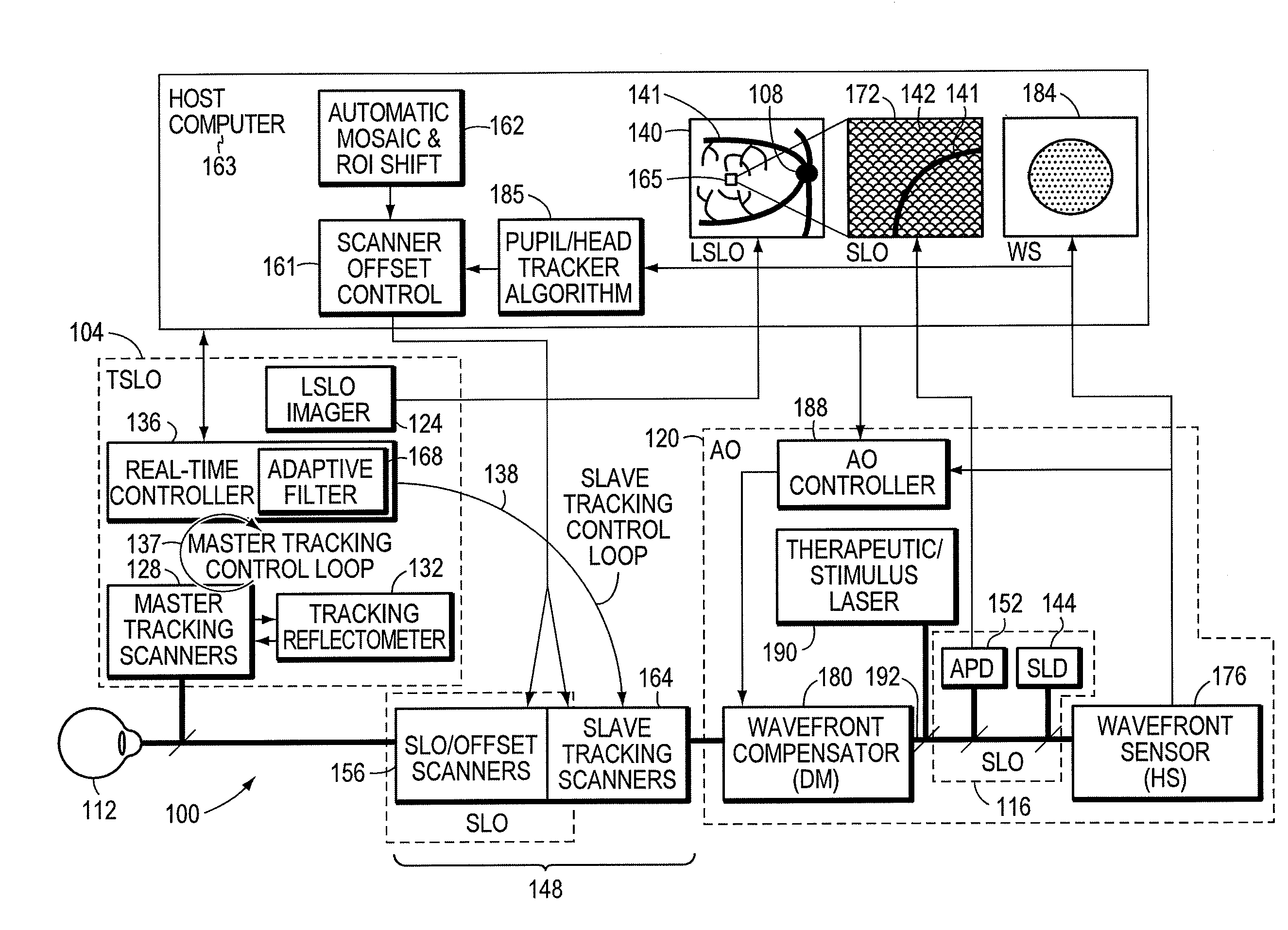
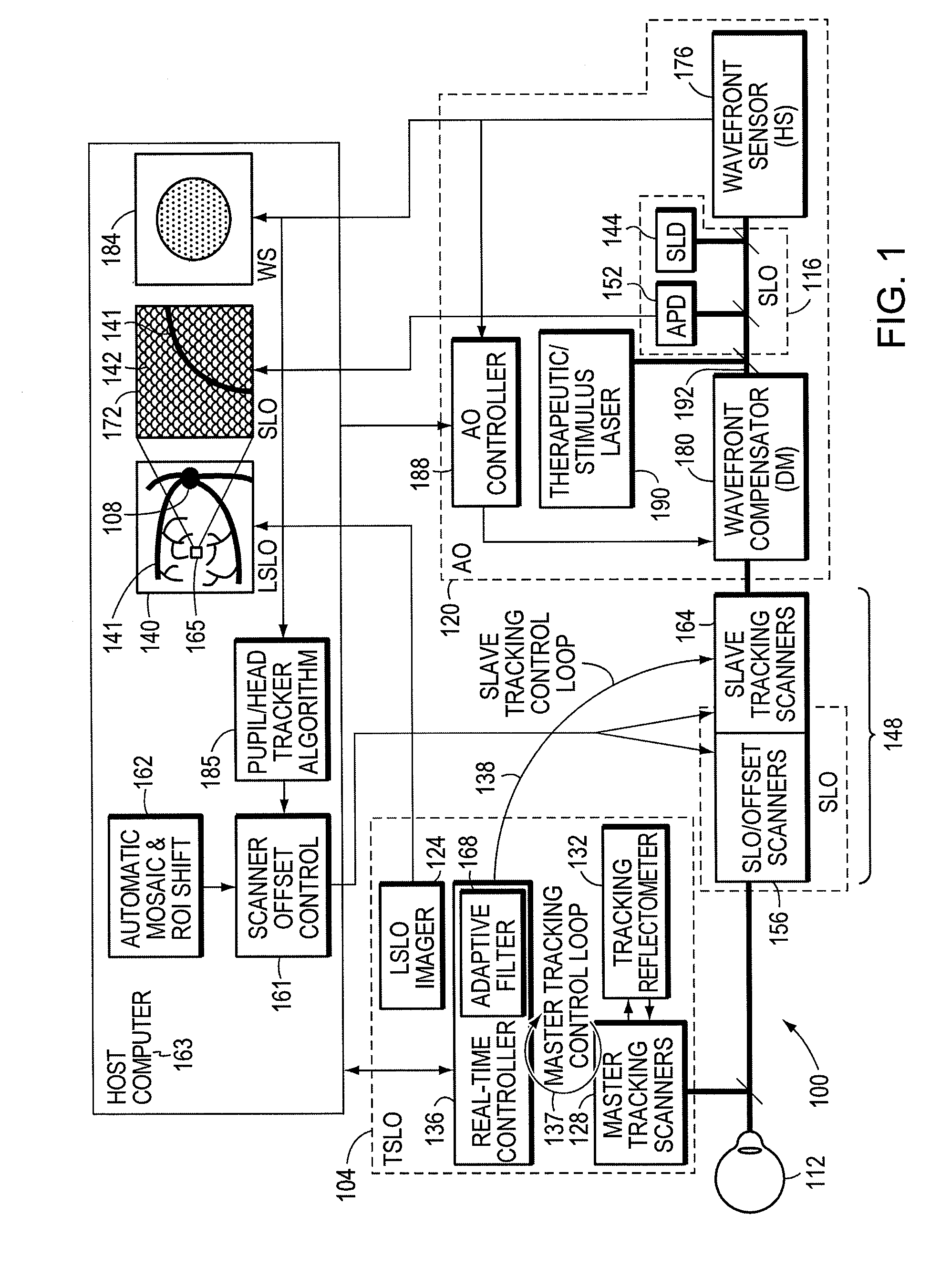
[0034]FIG. 1 shows an illustrative embodiment of a retinal imaging system 100 including three subsystems: a first module 104 for retinal tracking, a second module for imaging 116, and a third module with adaptive optics 120. The first module or retinal tracker 104 can stabilize to fixed and repeatable retinal coordinates and correct for the adverse effects of eye 112 motion. The retinal tracker 104 can include a wide-field line-scanning laser ophthalmoscope (T-LSLO, or TSLO). The second module or imaging apparatus 116 can be a flying-spot scanning laser ophthalmoscope 116, which can provide high-magnification confocal images. The third module or adaptive optics (AO) component 120 can sense wave-front distortion and correct for ocular aberrations.

[0035] Control of hardware and acquisition and processing of images and data from the sub-systems can be accomplished using a single software platform. The system, therefore, can present to the operator and / or clinician a wide-field view of...


PUM


Abstract

A system provides an optical image of an object. A first module tracks a reference feature of the object. A second module includes a source for an imaging beam, a scanning device to move the imaging beam along a portion of the object and a detection device receives a signal associated with an image of the portion of the object. The first module controls the position of the imaging beam relative to the reference feature to correct for the motion of the object. A third module detects a distortion of the object and compensates for the distortion.

Description

CROSS-REFERENCE TO RELATED APPLICATION [0001] This application claims the benefit of and priority to U.S. provisional patent application No. 60 / 794,359 filed Apr. 24, 2006, which is owned by the assignee of the instant application and the disclosure of which is incorporated herein by reference in its entirety.STATEMENT OF GOVERNMENT INTEREST [0002] This invention was made with government support under Contract Nos. R21EB003111 and R01EY14375 awarded by the National Institute of Health. The government may have certain rights in the invention.FIELD OF THE INVENTION [0003] The invention relates generally to a method and apparatus for optical imaging including a module to correct for movement of an object and a module to correct for distortions of an object. BACKGROUND OF THE INVENTION [0004] Adaptive optics (AO) instruments are used in ophthalmology to sense and correct ocular aberrations and provide high transverse resolution imaging. AO systems couple a wavefront sensor (e.g., Hartma...

Claims


Application Information

Patent Timeline
IPC IPC(8): A61B3/10
CPCA61F9/008A61F2009/00846A61F2009/00848G01S17/58G01S17/66A61B3/102G01B9/0203G01B9/02091G01B9/02068G01B9/02077G01S17/88A61B3/103
Inventor HAMMER, DANIEL X.FERGUSON, R. DANIELIFTIMIA, NICUSOR V.USTUN, TEOMAN E.
Owner PHYSICAL SCI
Why Eureka
Try Eureka