Devices to Facilitate Alignment and Focussing of a Fundus Camera

a technology of fundus camera and device, which is applied in the field of devices for aligning and focusing of fundus cameras, can solve the problems of increasing the mechanical complexity of the system and reducing the change in image magnification

Inactive Publication Date: 2007-11-01
VISION BIOSYST
View PDF16 Cites 30 Cited by
  • Summary
  • Abstract
  • Description
  • Claims
  • Application Information

AI Technical Summary

Benefits of technology

[0018]FIG. 4d is a graph showing the effect of varying the ratio of powers of the fixed lenses 14&15 on the movement of focal plane of the projected focus aid mark with movement of the focussing lens 10. Line b indicates the relationship for a system with increased ratio of power of lens 15 over the power of lens 14, compared with that for line a.

Problems solved by technology

The afocal lens system required for this system has a disadvantage that the magnification of the image appearing at the camera imaging plane changes through a large range as the focus is adjusted and this varies the area of the fundus and the apparent brightness of the image through a large range.
This alternative allows the use of a lens of reduced or negative power as the focussing lens with a result that the change in image magnification is reduced, but the required cams or linkages increase the mechanical complexity of the system.

Method used


Image

  • Devices to Facilitate Alignment and Focussing of a Fundus Camera
  • Devices to Facilitate Alignment and Focussing of a Fundus Camera
  • Devices to Facilitate Alignment and Focussing of a Fundus Camera

Examples


Embodiment Construction

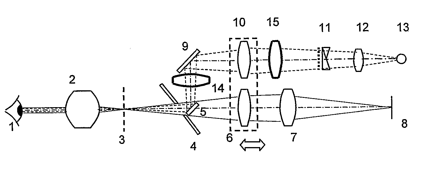
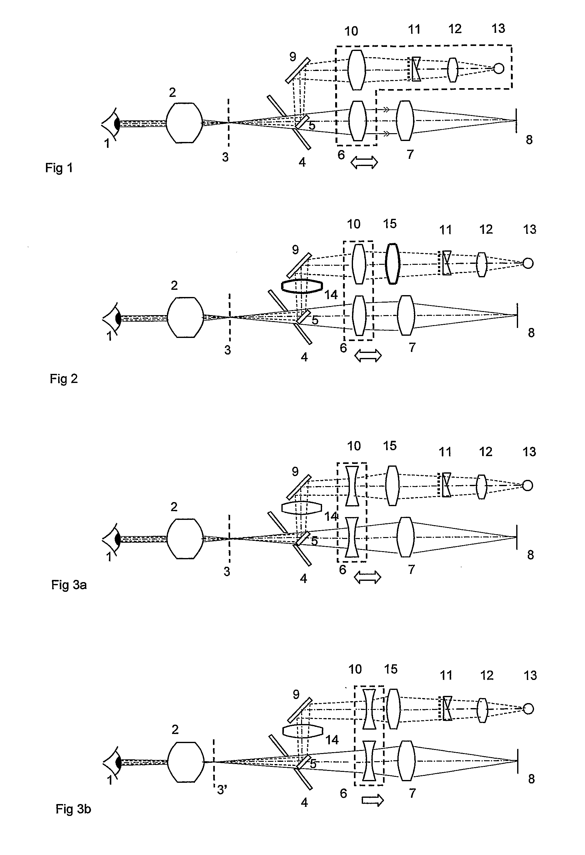
[0022] Referring now to the drawings, FIG. 1 shows one example of a fundus camera with projected focus aid marks as described in U.S. Pat. No. 4,187,014. FIG. 1 shows the imaging system of the fundus camera which comprises an objective lens 2 to collect light from the subject eye 1, a hole in the middle of an illumination reflecting mirror 4 to allow light to pass to the focussing lens 6 and imaging lens 7 and then to the imaging device 8. In this invention, the focus aid mark projection system is implemented via components 5,9,10,11,12,13. Note that prisms 11 are shown rotated 90 deg about the optical axis, for clarity. Light from source 13 is collected by the condenser lens 12 then split by the pair of splitting prisms and associated slit mask 11 into two diverging beams, then focussed by lens 10 and reflected by mirrors 9 and 5 so as to pass through two holes in mirror 4 either side of a central hole provided for the light passing to the imaging system 8 and thus to focus an imag...


PUM


Abstract

A fundus camera is provided with a focus aid mark projection system (5, 9, 10, 11, 12, 13) that includes a focus aid mark focussing lens (10) and other optical components such that the focus aid mark focussing lens (10) is attached to the focussing lens (6) of the imaging system and moves with that lens, thereby maintaining the focal planes of the focus aid mark projection system and the imaging system co-planar. An associated alignment mark projection system (35, 34, 33, 32) includes optics that utilise part of the existing fundus camera illumination system (35) to project a plurality of alignment marks onto the iris of the subject eye.

Description

TECHNICAL FIELD [0001] This invention relates to improvements in devices for alignment and focussing of a fundus camera. [0002] A fundus camera is used to capture an image of the fundus (posterior portion of the eye, including the retina and blood vessels). This fundus image can be examined by a third party or compared to fundus images taken at an earlier date, to facilitate diagnosis of retinal disease. The fundus camera comprises an objective lens to form an image of the fundus of the eye, other lenses to form an image on the recording plane of a camera, and an illumination system to project light into the eye so that the fundus image is sufficiently bright that an image may be captured on the camera. To enable a useful image to be formed without unacceptable reflections from the anterior parts of the eye (including the cornea, iris and vitreous lens) the fundus camera must be aligned very accurately. For capture of fundus images without mydriasis to dilate the pupil, the required...

Claims


Application Information

Patent Timeline
Patent Type & Authority Applications(United States)
IPC IPC(8): A61B3/14A61B3/12A61B3/13A61B3/15
CPCA61B3/152A61B3/145
Inventor KOENNECKE, GREG
Owner VISION BIOSYST
Why Eureka
Try Eureka