
Photocatalytic window and method of making same

Inactive Publication Date: 2007-11-01
GUARDIAN GLASS LLC
View PDF97 Cites 36 Cited by
  • Summary
  • Abstract
  • Description
  • Claims
  • Application Information

AI Technical Summary

Benefits of technology

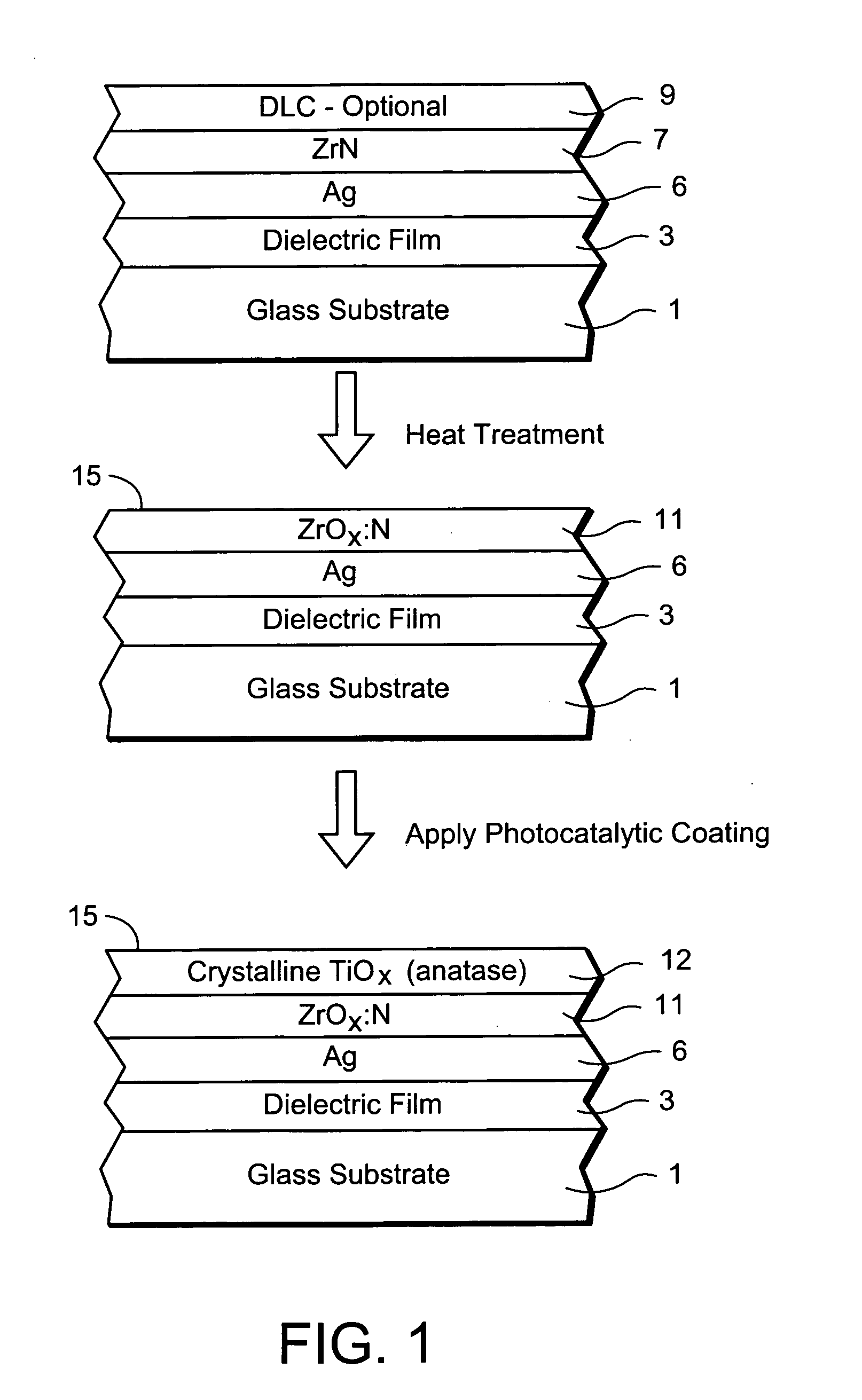
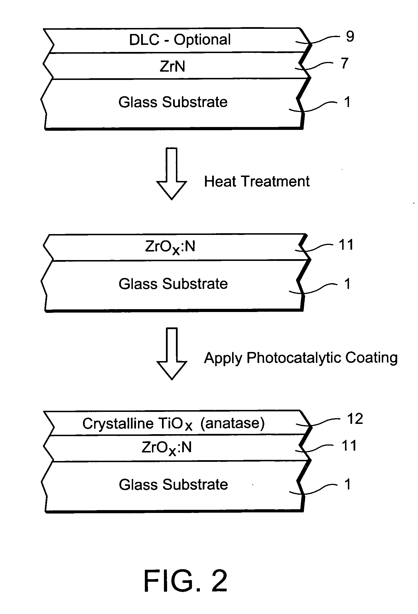
[0012]In certain example embodiments of this invention, a photocatalytic layer (e.g., of or including crystalline TiO2 such as the anatase type) is provided over a zirconium oxide inclusive layer in a window, table-top, or the like. Such embodiments may or may not be used in combination with the silver inclusive anti-bacterial / anti-fungal feature discussed herein (e.g., the photocatalytic layer and the zirconium oxide inclusive layer may both be porous and may both be located over the silver in anti-bacterial / anti-fungal embodiments). The use of the zirconium oxide layer under the photocatalytic layer significantly improves the durability of the coated article, while permitting the article to realize low contact angle (θ) and self-cleaning which are both desirable in many situations.
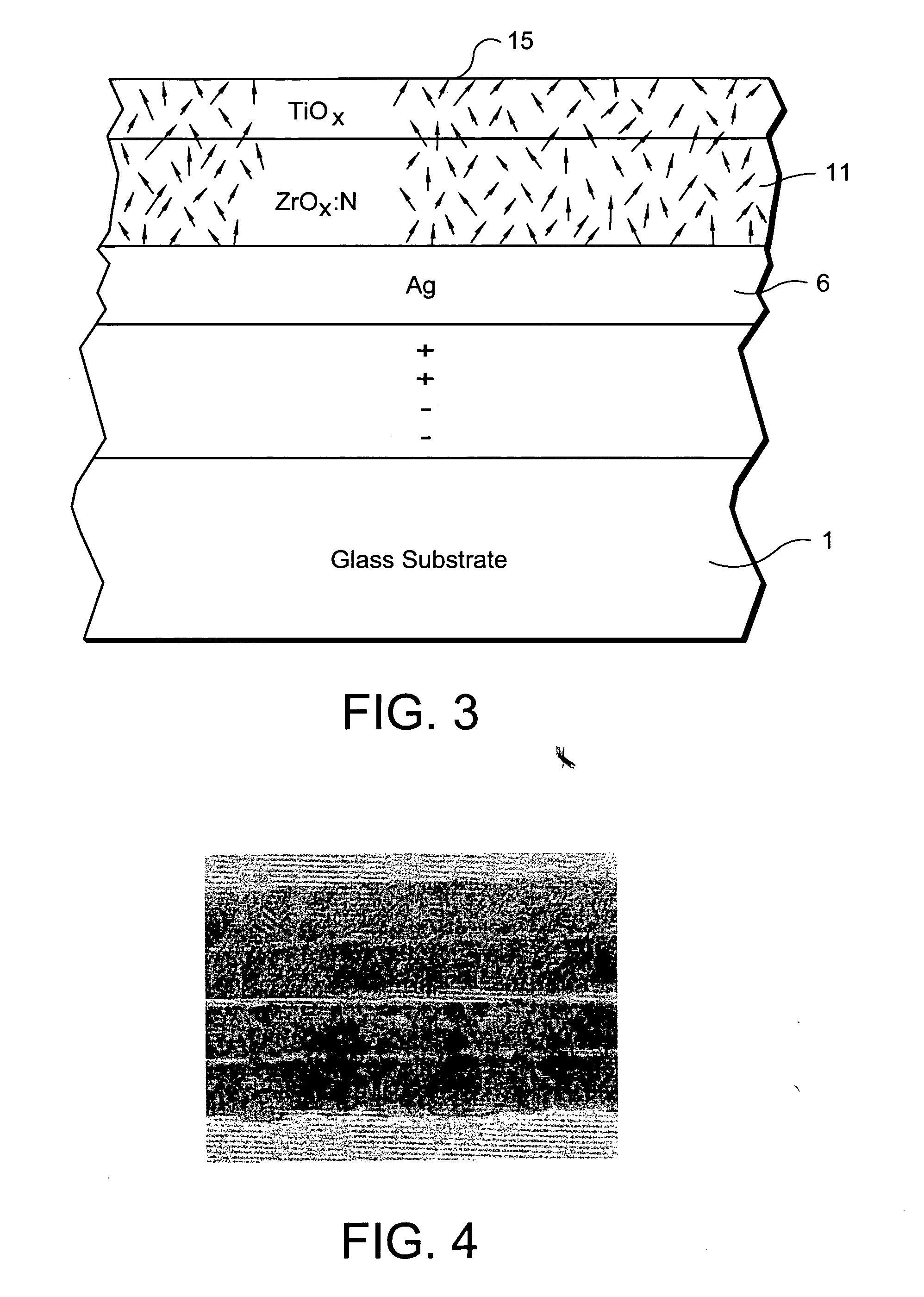
[0014]Methods of making such coated articles for use in windows or the like are also provided. In certain example embodiments, a layer of or including zirconium nitride and / or zirconium oxide is formed on a glass substrate. In certain example instances, the zirconium nitride and / or oxide layer may be doped with other material(s) such as F, C and / or Ce. Optional fluorine (F) and carbon (C) dopants, for example, have been found to increase visible transmission of the coated article. While the zirconium nitride and / or oxide is formed on the glass substrate, there may be other layer (e.g., a silver based layer) therebetween; thus, the word “on” is not limited to directly on herein. Optionally, a carbon inclusive layer (e.g., diamond-like carbon (DLC)) may be provided over the zirconium inclusive layer. This carbon inclusive layer may be used to generate energy during heat treatment (HT) for transforming at least another layer in the coating so as to form a new post-HT layer(s) which was not present in the post-HT form before the HT (e.g., the zirconium nitride may be transformed into zirconium oxide as a result of the HT; and / or the zirconium based layer may have a degree of tensile stress therein post-HT which was not present in the layer pre-HT). The coated article including the zirconium nitride and / or oxide layer, the silver based layer (optional), and the carbon inclusive layer (optional) is heat treated for thermal tempering or the like. As a result of the heat treating, the zirconium nitride inclusive layer if used transforms into a layer comprising zirconium oxide (this post-HT zirconium oxide layer may or may not include nitrogen in different embodiments). The post-HT layer of or including zirconium oxide is scratch resistant (SR) in certain example embodiments. In certain example instances, the heat treatment also causes a change in stress of the zirconium based layer (e.g., the zirconium based layer may have a degree of tensile stress therein post-HT which was not present in the layer pre-HT), such stress permitting crystal grain boundaries and / or tiny pinholes to be present in the layer to allow optional silver migration therethrough over time. Following the heat treatment, a photocatalytic layer (e.g., of or including crystalline TiO2 such as of the anatase type) can be formed on the glass substrate over the zirconium oxide inclusive layer and over the optional silver based layer. The photocatalytic layer may be formed using a colloidal solution, and / or a sol-gel, with subsequent curing, in certain example embodiments of this invention.

Problems solved by technology

Unfortunately, DLC tends to oxidize and burn off at temperatures of from approximately 380 to 400 degrees C. or higher, as the heat treatment is typically conducted in an atmosphere including oxygen.
Thus, it will be appreciated that DLC as a protective overcoat cannot withstand heat treatments (HT) at the extremely high temperatures described above which are often required in the manufacture of vehicle windows, IG window units, glass table tops, and / or the like.
Accordingly, DLC cannot be used alone as a coating to be heat treated, because it will oxidize during the heat treatment and substantially disappear as a result of the same (i.e., it will burn off).
Certain other types of scratch resistant materials also are not capable of withstanding heat treatment sufficient for tempering, heat strengthening and / or bending of an underlying glass substrate.

Method used


Image

  • Photocatalytic window and method of making same
  • Photocatalytic window and method of making same
  • Photocatalytic window and method of making same

Examples


Embodiment Construction

[0032]Referring now more particularly to the accompanying drawings in which like reference numerals indicate like parts or layers throughout the several views.

[0033]In certain example embodiments of this invention, there is provided a method of making a coated article (e.g., window such as for a vehicle, building, shower door, or the like) that is capable of being heat treated so that after being heat treated (HT) the coated article is scratch resistant to an extent more than uncoated glass. Moreover, certain example embodiments of this invention relate to a window having anti-fungal / anti-bacterial properties and / or self-cleaning properties, and a method of making the same. Coated articles according to certain example embodiments of this invention may be used in the context of shower door windows, architectural windows, vehicle windows, IG window units, picture frame windows, or the like. While coated articles according to this invention are particularly adapted for use in windows, ...


PUM

PropertyMeasurementUnit
Fractionaaaaaaaaaa
Fractionaaaaaaaaaa
Fractionaaaaaaaaaa

Abstract

Certain example embodiments of this invention relate to a photocatalytic coated article and a method of making the same. In certain example embodiments, a coated article includes a zirconium nitride and / or oxide inclusive layer before heat treatment (HT). The coated article is heat treated so that following heat treatment (e.g., thermal tempering) a zirconium oxide based layer is provided. A photocatalytic layer (e.g., of an oxide of titanium) may be formed over zirconium oxide based layer following heat treatment.

Description

[0001]This invention relates to a photocatalytic window having self-cleaning properties, and a method of making the same.BACKGROUND OF THE INVENTION[0002]Vehicle windows (e.g., windshields, backlites, sunroofs, and sidelites) are known in the art. For purposes of example, vehicle windshields typically include a pair of bent glass substrates laminated together via a polymer interlayer such as polyvinyl butyral (PVB). It is known that one of the two glass substrates may have a coating (e.g., low-E coating) thereon for solar control purposes such as reflecting IR and / or UV radiation, so that the vehicle interior can be more comfortable in certain weather conditions. Conventional vehicle windshields are made as follows. First and second flat glass substrates are provided, one of them optionally having a low-E coating sputtered thereon. The pair of glass substrates are washed and booked together (i.e., stacked on one another), and then while booked are heat bent together into the desired...

Claims


Application Information

Patent Timeline
IPC IPC(8): B32B17/06B05D3/02B05D1/36
CPCC03C17/34C03C2218/355C03C17/3423C03C17/3435C03C17/3441C03C17/36C03C17/3621C03C17/3626C03C17/3634C03C17/3644C03C17/3681C03C2204/02C03C2217/212C03C2217/22C03C2217/425C03C2217/479C03C2217/71C03C2217/75C03C2217/78C03C2218/322C03C2218/328C03C17/3417
Inventor VEERASAMY, VIJAYEN S.THOMSEN, SCOTT V.NUNEZ-REGUEIRO, JOSE
Owner GUARDIAN GLASS LLC
Learn More