Semiconductor device having a gate contact structure capable of reducing interfacial resistance and method of forming the same

a technology of interfacial resistance and contact structure, which is applied in the direction of semiconductor devices, electrical devices, transistors, etc., can solve the problems of increasing electric resistance, resistive capacitive delay, and increasing line width, and achieve the effect of reducing line width and increasing resistan

Inactive Publication Date: 2007-11-08
SAMSUNG ELECTRONICS CO LTD
View PDF2 Cites 21 Cited by
  • Summary
  • Abstract
  • Description
  • Claims
  • Application Information

AI Technical Summary

Problems solved by technology

However, with conductive patterns such as gate electrodes and interconnections, the line width decrease results in an electric resistance increase which leads to resistive capacitive (RC) delay.
Technical problems due to the line width decrease become more serious for the gate electrode than the interconnections made of metallic material.
Notwithstanding the low specific resistance of tungsten, if the tungsten comes in direct contact with a gate insulating layer, technical problems such as degradation of reliability of the gate insulating layer may occur.
This increase of contact resistance causes various technical problems.
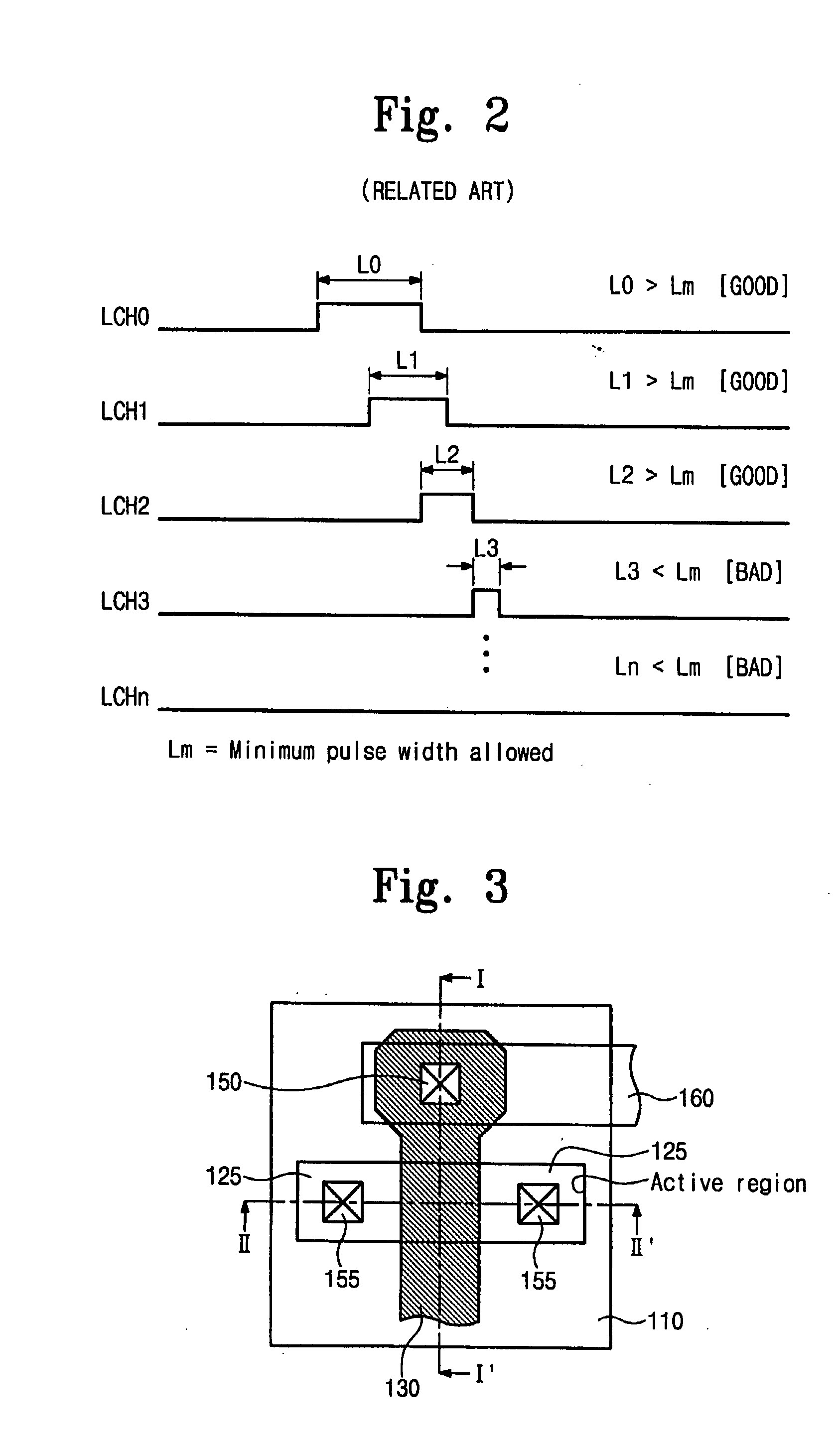
For example, as shown in FIG. 2, an increase of interfacial contact resistance due to non-ohmic contact results in a signal delay of the circuit forming an inverter.
Therefore, a width of a generating pulse may be shorter than a length required in the nth latch circuit, and thus the FLASH memory may not operate normally.
These technical problems may be commonly found in most general metal gate structures having a polysilicon layer.
Nonetheless, due to pitting of active region, it is difficult to overcome these technical problems by the methods suggested by related art technologies.
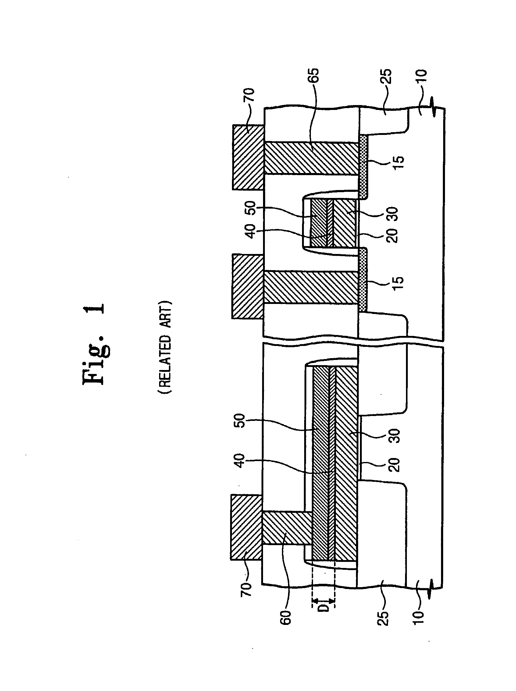
However, this additional etching may cause an excessive-etching of the impurity regions 15 (i.e. active-fitting).

Method used


Image

  • Semiconductor device having a gate contact structure capable of reducing interfacial resistance and method of forming the same
  • Semiconductor device having a gate contact structure capable of reducing interfacial resistance and method of forming the same
  • Semiconductor device having a gate contact structure capable of reducing interfacial resistance and method of forming the same

Examples


Embodiment Construction

[0034]Korean Patent Application No. 2006-40121, filed on May 3, 2006, in the Korean Intellectual Property Office, and entitled: “Semiconductor Devices Having Gate Contact Structure Capable of Reducing Interfacial Resistance and Methods of Forming the Same,” is incorporated by reference herein in its entirety.

[0035]The present invention will now be described more fully hereinafter with reference to the accompanying drawings, in which exemplary embodiments of the invention are illustrated. The invention may, however, be embodied in different forms and should not be construed as limited to the embodiments set forth herein. Rather, these embodiments are provided so that this disclosure will be thorough and complete, and will fully convey the scope of the invention to those skilled in the art.

[0036]In the drawing figures, the dimensions of layers and regions may be exaggerated for clarity of illustration. It will also be understood that when a layer or element is referred to as being “on...


PUM

PropertyMeasurementUnit
conductiveaaaaaaaaaa
thicknessaaaaaaaaaa
dielectricaaaaaaaaaa

Abstract

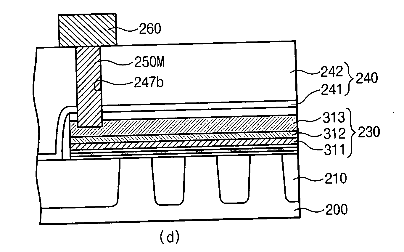
A semiconductor device has a gate contact structure, including a semiconductor substrate, a polycrystalline silicon layer used as a gate electrode of a transistor, a middle conductive layer, a top metal layer having an opening exposing the polycrystalline silicon layer, and a contact plug directly contacting the polycrystalline silicon layer through the opening.

Description

BACKGROUND OF THE INVENTION[0001]1. Field of the Invention[0002]The present invention relates to a semiconductor device and method of forming the same. More particularly, the present invention relates to a semiconductor device having a gate contact structure capable of reducing interfacial resistance and a method of forming the same.[0003]2. Description of the Related Art[0004]The line width of patterns composing a semiconductor device constitute an important parameter which determines an integration density of the semiconductor device. In order to increase the integration density of the semiconductor device, the line width of the patterns may be decreased to a level corresponding to an increase of the integration density. However, with conductive patterns such as gate electrodes and interconnections, the line width decrease results in an electric resistance increase which leads to resistive capacitive (RC) delay. Conventional gate electrodes may be made of a silicon-based conductiv...

Claims


Application Information

Patent Timeline
Patent Type & Authority Applications(United States)
IPC IPC(8): H01L29/788H01L21/336
CPCH01L21/823462H01L21/823475H01L29/7883H01L27/11521H01L27/11524H01L27/115H10B69/00H10B41/30H10B41/35H01L21/28H01L21/18
Inventor KANG, CHANG-SEOKSHIN, YOO-CHEOLCHOI, JUNG-DALSEL, JONG-SUNKIM, JU-HYUNGJEON, SANG-HUN
Owner SAMSUNG ELECTRONICS CO LTD
Why Eureka
Try Eureka