Structure for composite materials of positive temperature coefficient thermistor devices and method of making the same

a technology of positive temperature coefficient and composite materials, which is applied in the direction of positive temperature coefficient thermistors, resistor details, insulating substrate metal adhesion improvement, etc., can solve the problems of insufficient interfacial joint strength of conductive crystallized polymeric composite materials filled with carbon black, high energy consumption, and complex process, etc., to achieve the effect of greatly simplifying the process

Inactive Publication Date: 2002-09-12
PROTECTRONICS TECH CORP
View PDF0 Cites 10 Cited by
  • Summary
  • Abstract
  • Description
  • Claims
  • Application Information

AI Technical Summary

Benefits of technology

[0012] Another object of the present invention is to provide a structure for composite materials of a positive temperature coefficient thermistor device and a method of making the same for lowering down the interfacial resistance between metal electrodes and the polymeric composite material plaque having the carbon black.
[0013] Yet another object of the present invention is to provide a structure for composite materials of a positive temperature coefficient thermistor device and a method of making the same, which can fit into the well-developed printed circuit board process and utilize the plaque fabrication method. Thus the process can be simpler.
[0016] Moreover, because the tight integration of the carbon black of the porous structure of the top metal layer with the conductive polymeric composite material, the interfacial resistance between the metal electrodes and the conductive polymeric composite material is effectively lowered down.
[0017] Furthermore, because existing printed circuit boards can be used as the metal laminated material of the present invention, the well-developed printed circuit board process can be used directly in the process of the thermistor device. Manufacturing the thermistor device by means of the plaque fabrication method of the printed circuit board process is simpler than the presently used continuous electroplating process for the whole roll of soft foil, and the process can be greatly simplified accordingly.

Problems solved by technology

Thus the energy consumption is enormous, and the process is very complicated.
However, the interfacial joint strength of the plaques made of the metal foil and conductive crystallized polymeric composite material filled with carbon black is not good enough after the thermal laminating process.
However, the carbon black cannot fully contact with the metal electrodes of the metal laminated plaque, and thus the interfacial resistance between metal laminated plaque and the conductive crystallized polymeric composite material plaque filled with carbon black rises.
Moreover, when a laminated structure of the multi-layer circuit is used to fabricate an over-current protection device or a temperature switch device, it has to face various kinds of regular or irregular temperature variation.
This leads to problems of joints between the electrodes of the metal laminated plaque and the conductive crystallized polymeric composite material plaque filled with carbon black.
However, the techniques disclosed by theses patents use the carbon black to be directly wedged to metal nodular protrusions, and the geometric shapes of the carbon black and of metal nodular protrusions are different, so the contact density is not very well.
Meanwhile, mobility of resin on the surface of carbon black is not good between carbon black and metal, the resin can just be adhered to the surface of the metal and thus, increase the interfacial resistance and effect its function.
The method is subjected to the foil material to proceed with a continuous electroplating process for a whole roll of foil, so that the fabrication method is limited.

Method used


Image

  • Structure for composite materials of positive temperature coefficient thermistor devices and method of making the same
  • Structure for composite materials of positive temperature coefficient thermistor devices and method of making the same
  • Structure for composite materials of positive temperature coefficient thermistor devices and method of making the same

Examples


Embodiment Construction

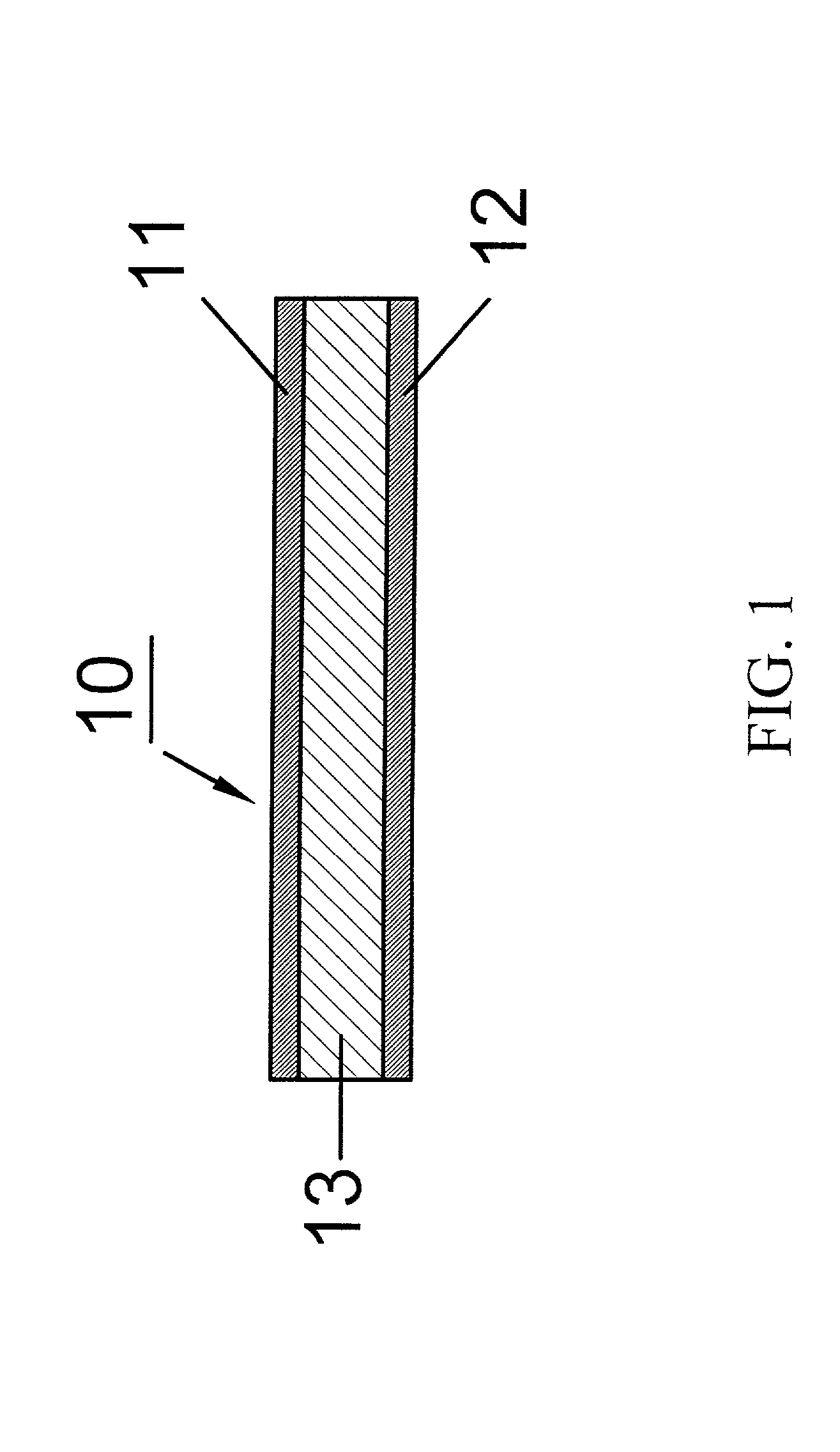
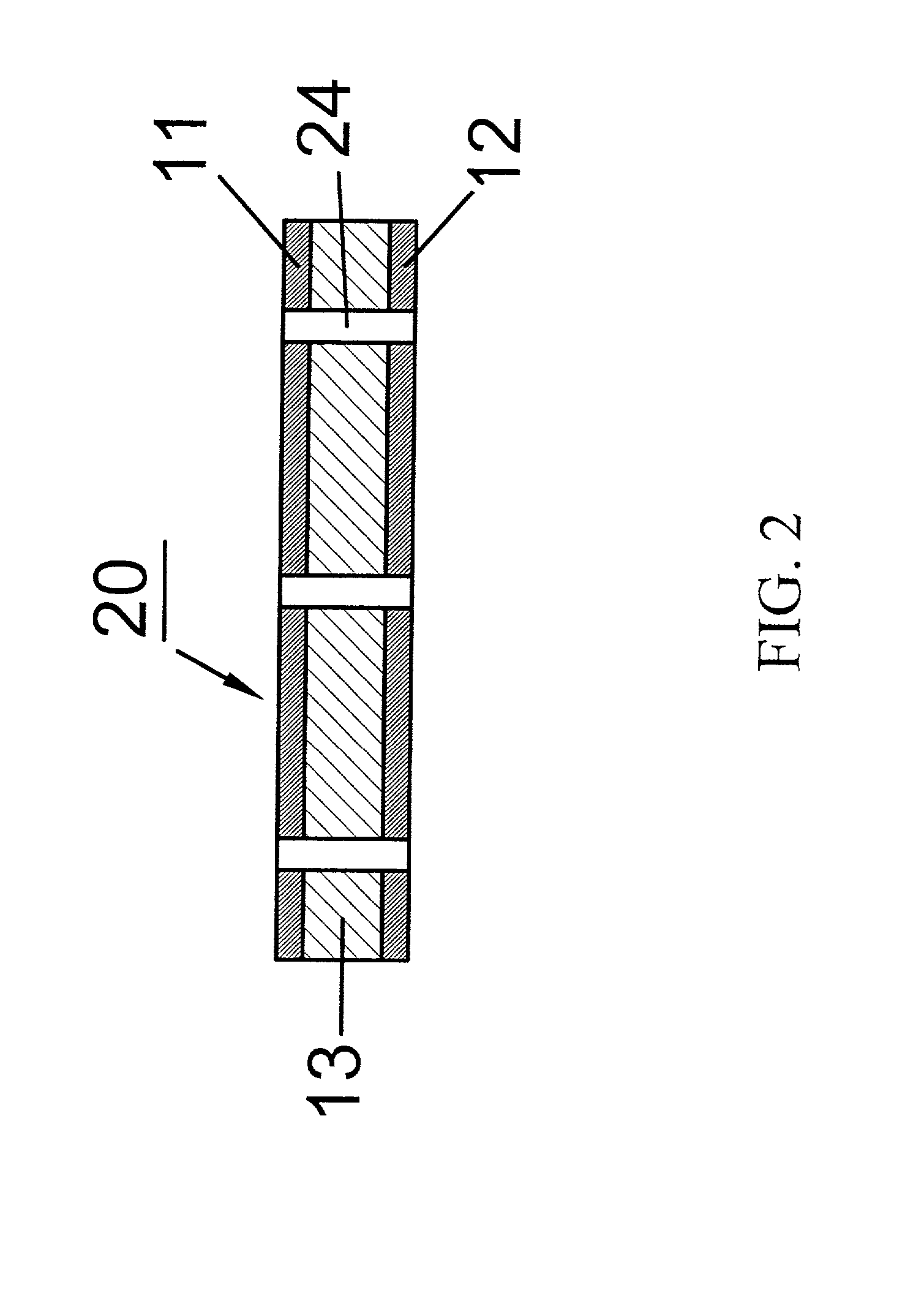
[0034] Referring to FIG. 1, a cross-sectional view of a metal laminated material 10 of an embodiment of the present invention is shown. An existing printed circuit board can be used here. A bottom metal layer 12 (a first electrode) and a top metal layer 11 (a second electrode) of the metal laminated material 10 are copper foil (other materials such as nickel foil, platinum, copper alloy, nickel alloy, platinum alloy, or other conductive materials can be used as well) with a thickness of 18 .mu.m. The insulating layer 13 can be a laminated material layer made of an epoxy resin layer, a polyimide resin layer, a glass fiber cloth impregnated with the epoxy resin, or a laminated material layer made of glass fiber cloth impregnated with a polyimide. The metal laminated material 10 with a size of 20 cm.times.20 cm is processed by a printed circuit board process to form a plurality of plate through holes 24 with a diameter of 0.05 cm and a pitch of 1 cm as shown in FIG. 2, so that the top ...


PUM

PropertyMeasurementUnit
thicknessaaaaaaaaaa
temperaturesaaaaaaaaaa
thicknessaaaaaaaaaa

Abstract

The present invention discloses a structure for composite materials of a positive temperature coefficient thermistor and a method of making the same. A carbon black is electroplated onto a surface of the metal electrodes of a metal laminated material to form a continuous porous structure having carbon black. Then a thermal laminating process is used to laminate the metal laminated material and a conductive crystallized polymeric composite material plaque filled with carbon black, to form a fine point between surfaces of the metal electrodes of metal laminated material and the conductive crystallized polymeric composite material plaque filled with carbon black. In the meantime, it can also lower down interfacial resistance by allowing carbon black particles of conductive crystallized polymeric composite material filled with carbon black to fully contact with the surface electroplated layer of the metal electrodes.

Description

BACKGROUND OF THE INVENTION[0001] 1. Field of the Invention[0002] The present invention relates to a structure for composite materials of a positive temperature coefficient thermistor and a method of making the same, and in particular, to a conductive polymeric composite material having carbon black utilized to a structure for composite materials of a positive temperature coefficient thermistor and a method of making the same.[0003] 2. Description of Related Art[0004] Thermistor devices are already widely used in many fields, such as temperature detection, security control, temperature compensation, and so on. In the past, a thermistor device has mainly utilized ceramic material.[0005] However ceramic material needs to be manufactured at high temperatures, in most cases, more than 900.degree. C. Thus the energy consumption is enormous, and the process is very complicated. Later on, a thermistor device utilizing a polymeric substrate is developed. As the manufacturing temperature of ...

Claims


Application Information

Patent Timeline
Patent Type & Authority Applications(United States)
IPC IPC(8): C25D5/16C25D15/02H01C1/14H01C7/02H05K1/16H05K3/38H05K3/46
CPCC25D5/16C25D15/02H01C1/1406H01C7/027H05K1/167H05K3/384H05K3/4623H05K2201/0323H05K2201/09536H05K2203/0307H05K2203/0723Y10T29/49091Y10T29/49083Y10T29/49082Y10T29/49098Y10T29/49101Y10T29/49087Y10T29/49085C25D5/605C25D5/623
Inventor HWANG, REN-HAURLIU, DER-YANGLIN, CHEN-RON
Owner PROTECTRONICS TECH CORP
Why Eureka
Try Eureka