High frequency divider with input-sensitivity compensation

a high-frequency divider and input-sensitivity compensation technology, applied in the field of frequency dividers, can solve the problems of not meeting users' requests on actual use, injection-locked frequency dividers are only suitable for narrow-band communication systems with low transferring rate, and the power level of input signals is increased, so as to reduce the power consumption of input signals, increase the frequency range for dividing input signals, and reduce the effect of input signal power consumption

Inactive Publication Date: 2007-11-08
NAT CENT UNIV
View PDF5 Cites 15 Cited by
  • Summary
  • Abstract
  • Description
  • Claims
  • Application Information

AI Technical Summary

Benefits of technology

[0007] The main purpose of the present invention is to ad just an oscillation frequency by in putting a DC control voltage without changing the circuit structure to maintain a lowest power strength of an in put signal, to reduce a power consumption of the input signal and to increase the frequency range for dividing the input signal.

Problems solved by technology

Yet, regarding the operation under the deviated frequency, because the inner oscillating signal is no more synchronization with the input signal, a division is impossible even through the power level of the input signal is increased.
Therefore, the injection locked frequency divider is only suitable for narrow-band communication systems with low transferring rates.
Hence, the prior arts do not fulfill users' requests on actual use.

Method used


Image

  • High frequency divider with input-sensitivity compensation
  • High frequency divider with input-sensitivity compensation
  • High frequency divider with input-sensitivity compensation

Examples


Embodiment Construction

[0016] The following descriptions of the preferred embodiments are provided to understand the features and the structures of the present invention.

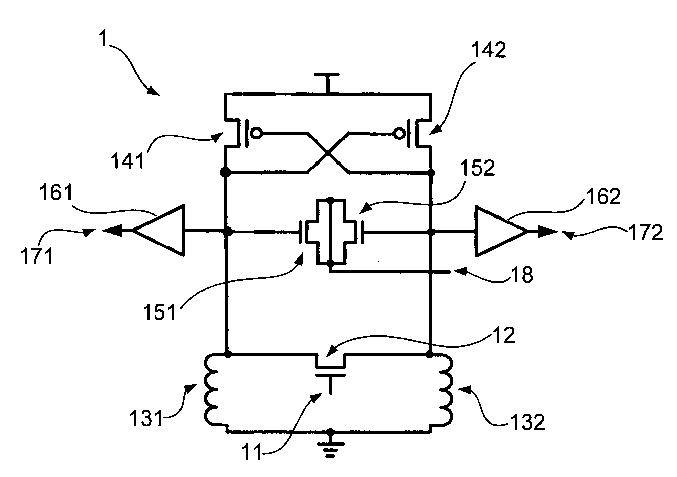
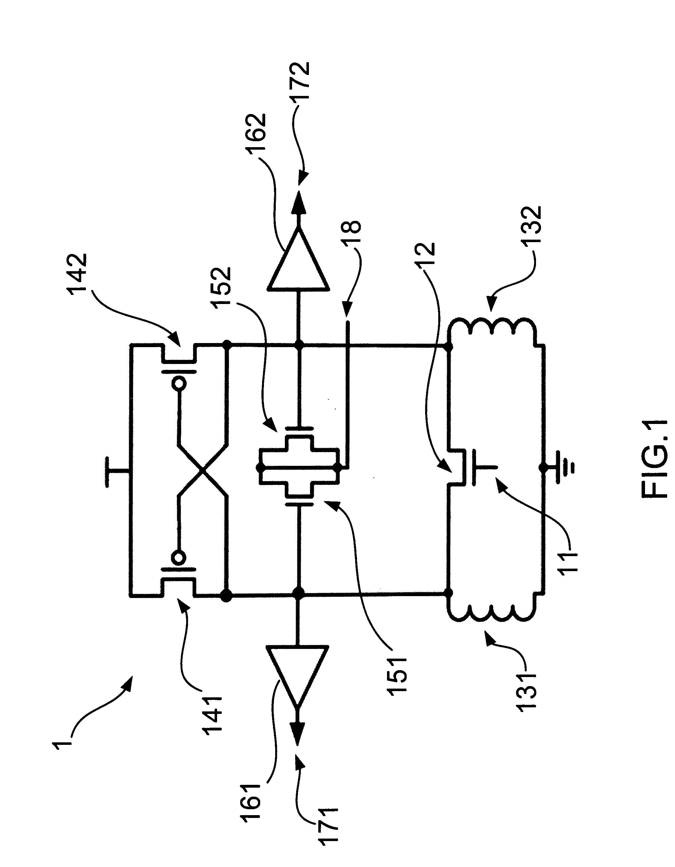
[0017] Please refer to FIG. 1, which is a structural view showing the first preferred embodiment according to the present invention. As shown in the figure, the present invention is a high frequency divider with input-sensitivity compensation, comprising an input terminal 11, an injection transistor 12, a first inductance 131, a second inductance 132, a first transistor 141, a second transistor 142, a third transistor 151, a fourth transistor 152, a first output buffer 161, a second output buffer 162, a first output terminal 171 (out+), a second output terminal 172 (out−), and a voltage control terminal, where the above components are connected electrically to form a cross-coupled inductor-capacitor (LC) structure.

[0018] Each transistor 141, 142, 151, 152 in the components is a metal oxide semiconductor (MOS) transistor, a high electron...


PUM


Abstract

A frequency divider, which has a cross-coupled inductor-capacitor (LC) structure or a ring structure, is inputted with a direct current (DC) control voltage from an input terminal. By doing so, the frequency divider can adjust an oscillation frequency; and further compensate the input power sensitivity, lower the power consumption and increase the division range. The frequency divider can be used in high-band/high-speed digital or analog communication systems.

Description

FIELD OF THE INVENTION [0001] The present invention relates to a frequency divider; more particuiarly, relates to, without changing a circuit structure, ad justing an oscillation frequency to obtain a compensation to a power sensitivity of an input, to reduce a power consumption of the input and to increase a frequency range for division. DESCRIPTION OF THE RELATED ARTS [0002] A general injection locked frequency divider has a structure of an oscillator, an LC structure or a ring structure, where signals are injected from an in injection terminal. When an injected signal has a phase synchronization to an inner oscillation signal, a division is done. The operative frequency of the circuit is decided by an oscillator, where the power required is low enough to be used in circuits with low power. Such a circuit is characterized in a big division ratio, a small locked frequency and a small phase noise. [0003] Generally speaking, the injection locked frequency divider has a smaller locked...

Claims


Application Information

Patent Timeline
Patent Type & Authority Applications(United States)
IPC IPC(8): H03L7/00
CPCH03B19/14H03L7/24H03K27/00
Inventor CHAN, YI-JENHUANG, FAN-HSIU
Owner NAT CENT UNIV
Why Eureka
Try Eureka