MIMO receiver with pooled adaptive digital filtering

a technology of adaptive digital filtering and receiver, applied in the field of wireless communication networks, can solve the problems of increasing inter-chip interference (ici) for low selectivity, and achieve the effect of reducing signal processing requirements

Inactive Publication Date: 2007-11-08
SAMSUNG ELECTRONICS CO LTD
View PDF22 Cites 9 Cited by
  • Summary
  • Abstract
  • Description
  • Claims
  • Application Information

AI Technical Summary

Benefits of technology

[0006]The present disclosure provides a technique for pooled adaptive digital filtering to reduce signal processing requirements.

Problems solved by technology

Thus, such filters eliminate the need for an intermediate frequency (IF) stage, but increase inter-chip interference (ICI) for low selectivity.

Method used


Image

  • MIMO receiver with pooled adaptive digital filtering
  • MIMO receiver with pooled adaptive digital filtering
  • MIMO receiver with pooled adaptive digital filtering

Examples


Embodiment Construction

[0018]FIGS. 1 through 6, discussed below, and the various embodiments used to describe the principles of the present disclosure in this patent document are by way of illustration only and should not be construed in any way to limit the scope of the disclosure. Those skilled in the art will understand that the principles of the present disclosure may be implemented in any suitably arranged wireless network.

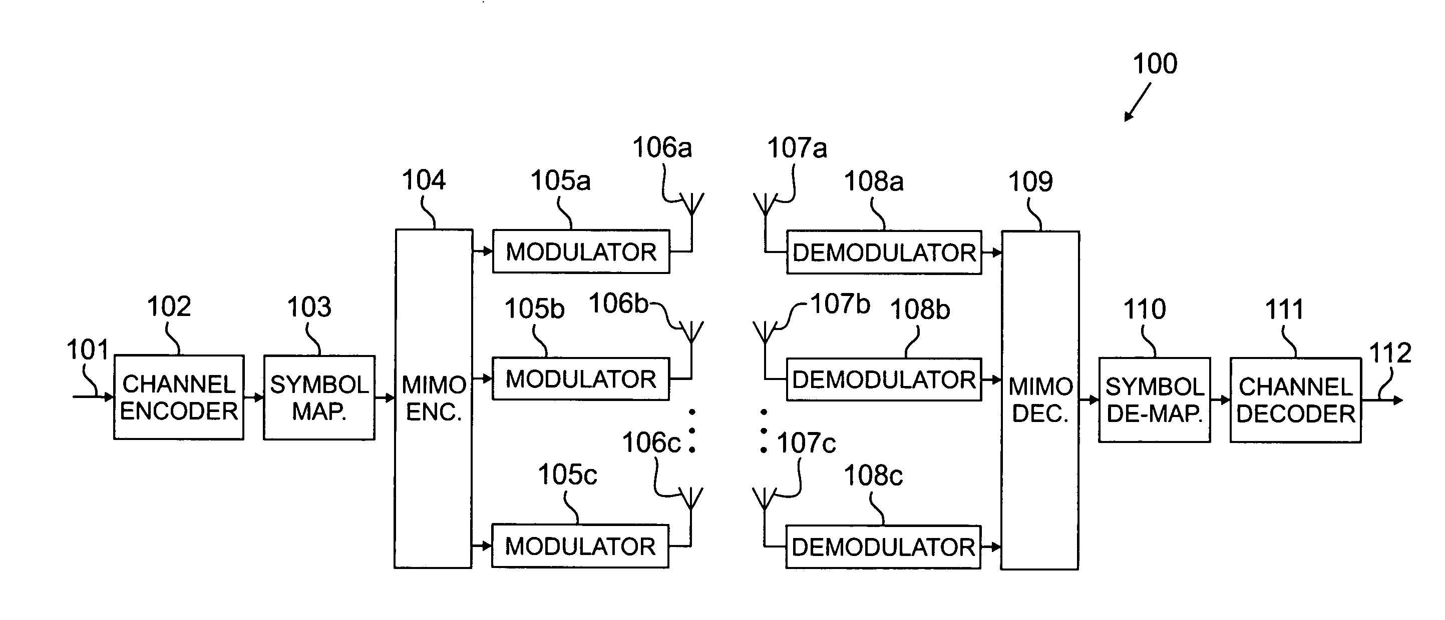
[0019]FIG. 1 illustrates a conventional multiple input, multiple output (MIMO) system 100. Input data stream 101 from a single user is encoded by channel encoder 102. After passing the encoded signal through symbol mapping module 103, the signal is passed to MIMO encoder 104. MIMO encoder 104 demultiplexes the signal into nT separate sub-streams. Each of the nT substreams are fed into one of modulators 105a, 105b and 105c (collectively referred to herein as modulator 105). Each of the nT substreams are transmitted out of one of transmit antennas 106a, 106b and 106c (collectively re...


PUM


Abstract

MIMO receiver with a reconfigurable pooled digital filter is disclosed. A processor sets parameters of the filter to minimize the number of instructions per second and the amount of power required by the filter to perform, while matching the filter to a transmitter filter. The processor uses an algorithm or a lookup table stored in memory to select the combination of filter parameters. The parameters may be selected from at least one of: a number of taps, a filter length, a word length, a coefficient quantization, a sampling rate, bits per sample, a sampling bit, a tap delay and a coefficient length. After selecting a combination of filter parameters, the processor sends a control signal to the adaptive filter. The pooled adaptive filter reconfigures itself in accordance with the selected filter parameters.

Description

CROSS-REFERENCE TO RELATED APPLICATION AND CLAIM OF PRIORITY[0001]The present application is related to U.S. Provisional Patent No. 60 / 798,429, filed May 5, 2006, entitled “MIMO RECEIVER WITH POOLED ADAPTIVE DIGITAL FILTERING THAT REDUCES SIGNAL PROCESSING”. U.S. Provisional Patent No. 60 / 798,429 is assigned to the assignee of the present application and is hereby incorporated by reference into the present disclosure as if fully set forth herein. The present application hereby claims priority under 35 U.S.C. §119(e) to U.S. Provisional Patent No. 60 / 798,429.TECHNICAL FIELD OF THE INVENTION[0002]The present application relates generally to wireless communication networks and, more specifically, to multiple input, multiple output (MIMO) receiver systems.BACKGROUND OF THE INVENTION[0003]Modern communications demand higher data rates and performance. Multiple input, multiple output (MIMO) antenna systems, also known as multiple-element antenna (MEA) systems, achieve greater spectral eff...

Claims


Application Information

Patent Timeline
Patent Type & Authority Applications(United States)
IPC IPC(8): A61F11/06H04B17/40
CPCH04B17/318H04B17/21
Inventor CLEVELAND, JOSEPH R.PISEK, ERAN
Owner SAMSUNG ELECTRONICS CO LTD
Why Eureka
Try Eureka