Fluid dispenser with internal pump

a dispenser and fluid technology, applied in the direction of positive displacement liquid engine, packaging food items, packaged goods, etc., can solve the problems of product contamination and product loss, inconvenient handling, waste of irrevocable products, etc., and achieve the effect of simple aperture, convenient access to and timely us

Inactive Publication Date: 2007-11-15
PENNCREEK
View PDF9 Cites 48 Cited by
  • Summary
  • Abstract
  • Description
  • Claims
  • Application Information

AI Technical Summary

Benefits of technology

[0004] The present invention recognizes the abundance of the prior art and contributes a specific advancement over that same art. Accordingly it is a particular intent of the present invention to provide a simple internal pump within a pouch reservoir forming a liquid dispenser of such a size and shape as to be carried in a pocket or hung about a neck and thus promotes convenient access to and timely use of the liquid product held within. Specifically, the pump located inside the liquid reservoir does not employ a one-way inlet valve for controlling liquid entering the pump chamber from the reservoir chamber as disclosed by the prior art. Instead, the common wall between the chambers has a simple aperture, a hole, which is blocked only when external pressure is applied by a finger to the outer reservoir wall which is pushed against the aperture, blocking the now pressurized pump fluid from transferring back to the reservoir chamber. The pressure of the pump fluid grows as the pump chamber is squeezed by an externally hand, when sufficient pressure is obtained the fluid opens the one-way exit valve and is dispersed until the pump chamber is emptied and the fluidic pressure therein drops. Upon removal of the finger and its induced pressure the elastic nature of the pump reforms its original volume and shape, drawing in a new dose of reservoir fluid through the now unblocked aperture in the common wall between chambers, this being the only recharge route available in that the exit valve has returned to it original closed state without pressurized fluid to keep it open. The aperture becomes unblocked absent the external pressure holding the reservoir wall against the aperture and the external wall has separated from the interior common wall and both reformed to their mutually apart relationship.
[0005] This simple pump, essentially a combination of two film walls, an exit valve, and a hole, requires a minimal number of components and materials. Yet, surprisingly, this design has proven to be very effective, durable, and highly reliable. Because the pump is easily squeezed by a variety of hand and finger configurations it has proven particularly useful to persons with limited hand mobility where a stripping action to discharge the fluid is problematic. Also, by placing the pump within the reservoir an overall flat, even stylish package is formed which significantly facilitates convenient access and timely usage. Finally, the simplicity of the overall design of the pump, reservoir, aperture and one valve, all of which can be constructed of various flexible polymer films of differing elastic properties, is of such a nature as to simply and reliable manufacture at an extremely low-cost while making use of a minimal amount of materials.
[0006] It is therefore the principal objective of this invention to provide a finger operated fluid pump dispenser offering the utmost simplicity and economy while also proving high reliable and convenience of use.

Problems solved by technology

Yet these containers are well known for wasting irrevocable product, inconvenient handling, unfortunate leaks, product contamination and product loss through evaporation.

Method used


Image

  • Fluid dispenser with internal pump
  • Fluid dispenser with internal pump
  • Fluid dispenser with internal pump

Examples


example 1

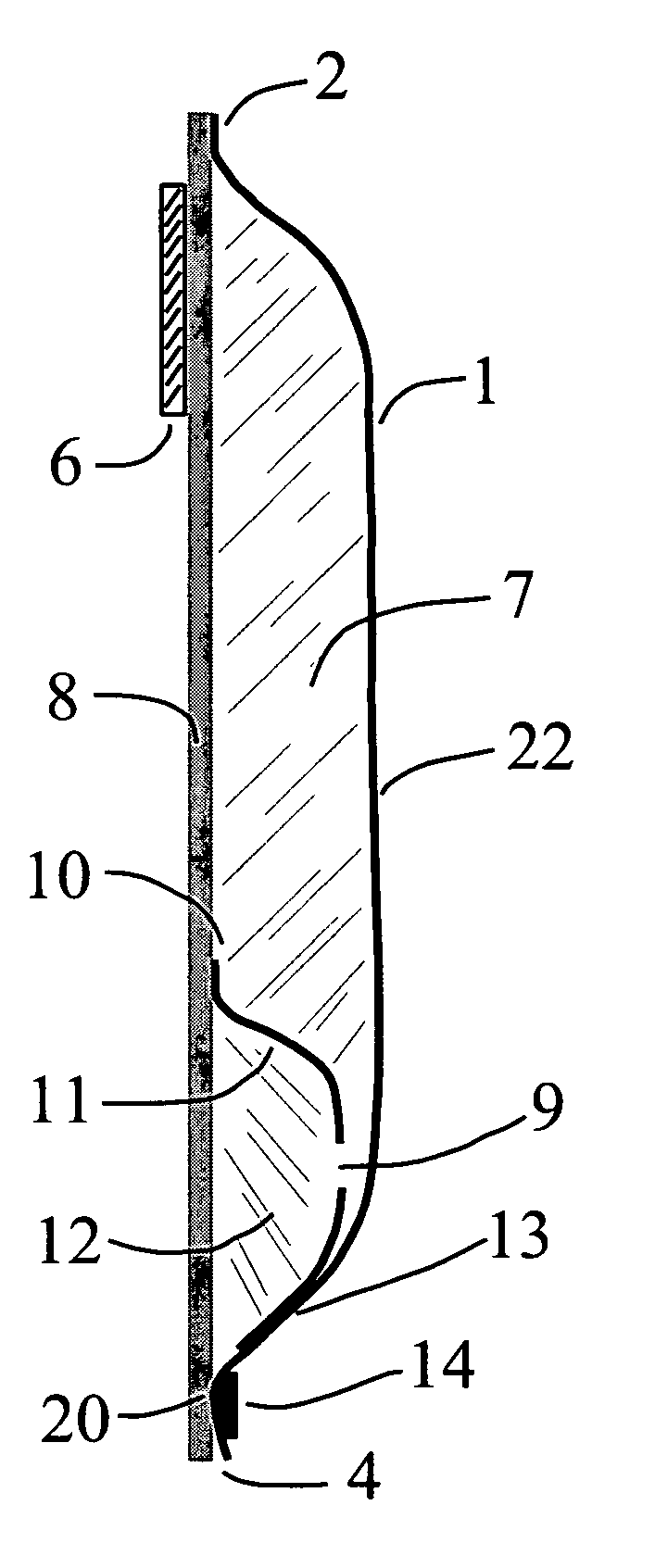
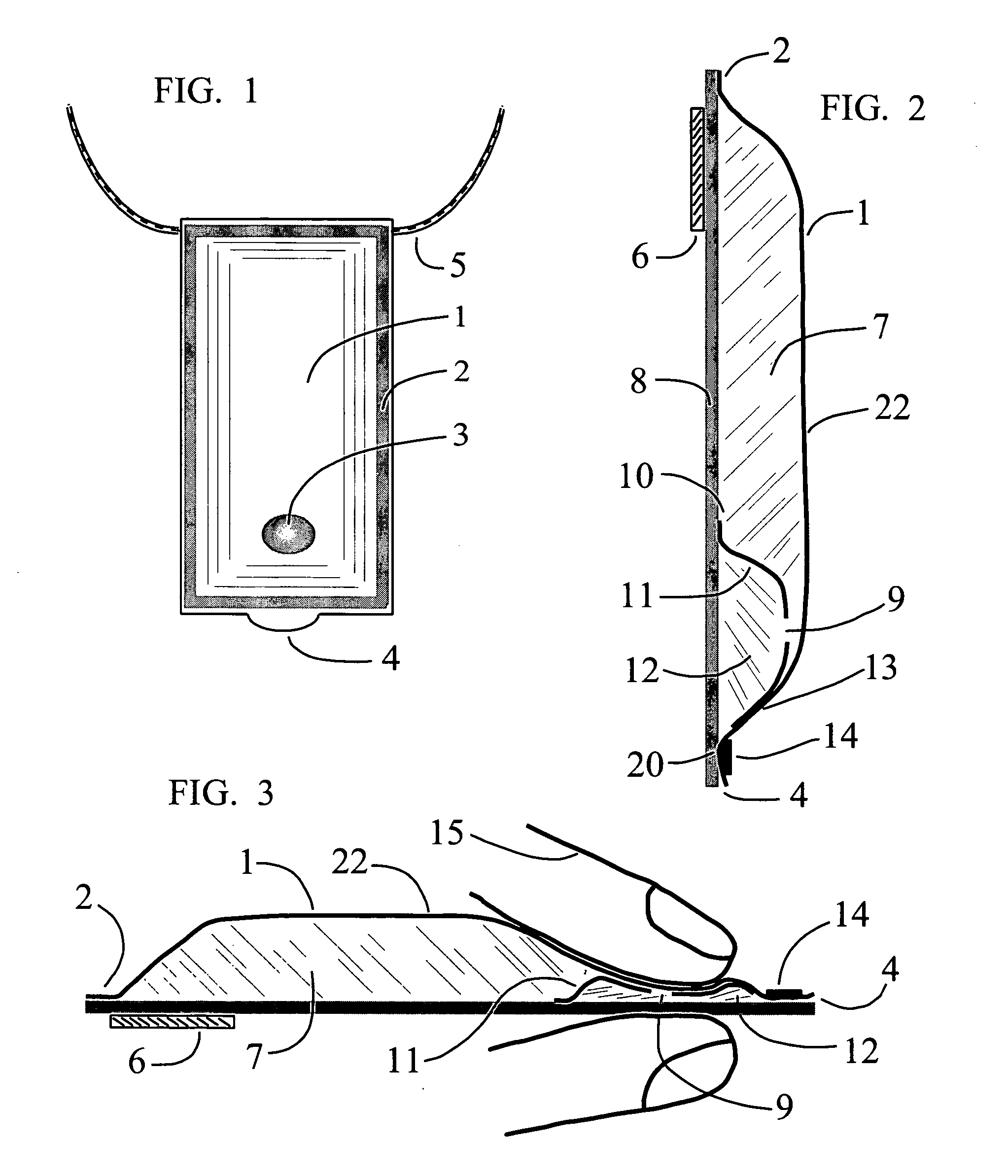
[0024] In FIG. 1 a frontal view of a rectangular shaped fluid dispenser 1 is illustrated. At the top is an attached lanyard 5 used to hang the dispenser 1 from a user's neck or other objects. On all sides are border seals 2 joining the front and rear walls forming the dispenser 1. At the bottom of the figure is an exit orifice 4 where the contained fluid product within is dispersed. On the surface of the dispenser 1 is a cuing means, a visual and / or tactile mark 3 indicating where hand, thumb, palm and / or finger pressure is to be applied to create sufficient internal pump pressure for fluid dispersement. When tactile in nature, such as a raised ridge on the surface, this mark 3 obviates the need for the user to look at the dispenser in order to determine where to apply pressure to an obscured pump located within the dispenser 1. FIG. 2 shows a cross sectional view of the fluid dispenser 1 wherein the reservoir chamber 7 is defined by the flexible front wall 22 joined by border seals...

example 2

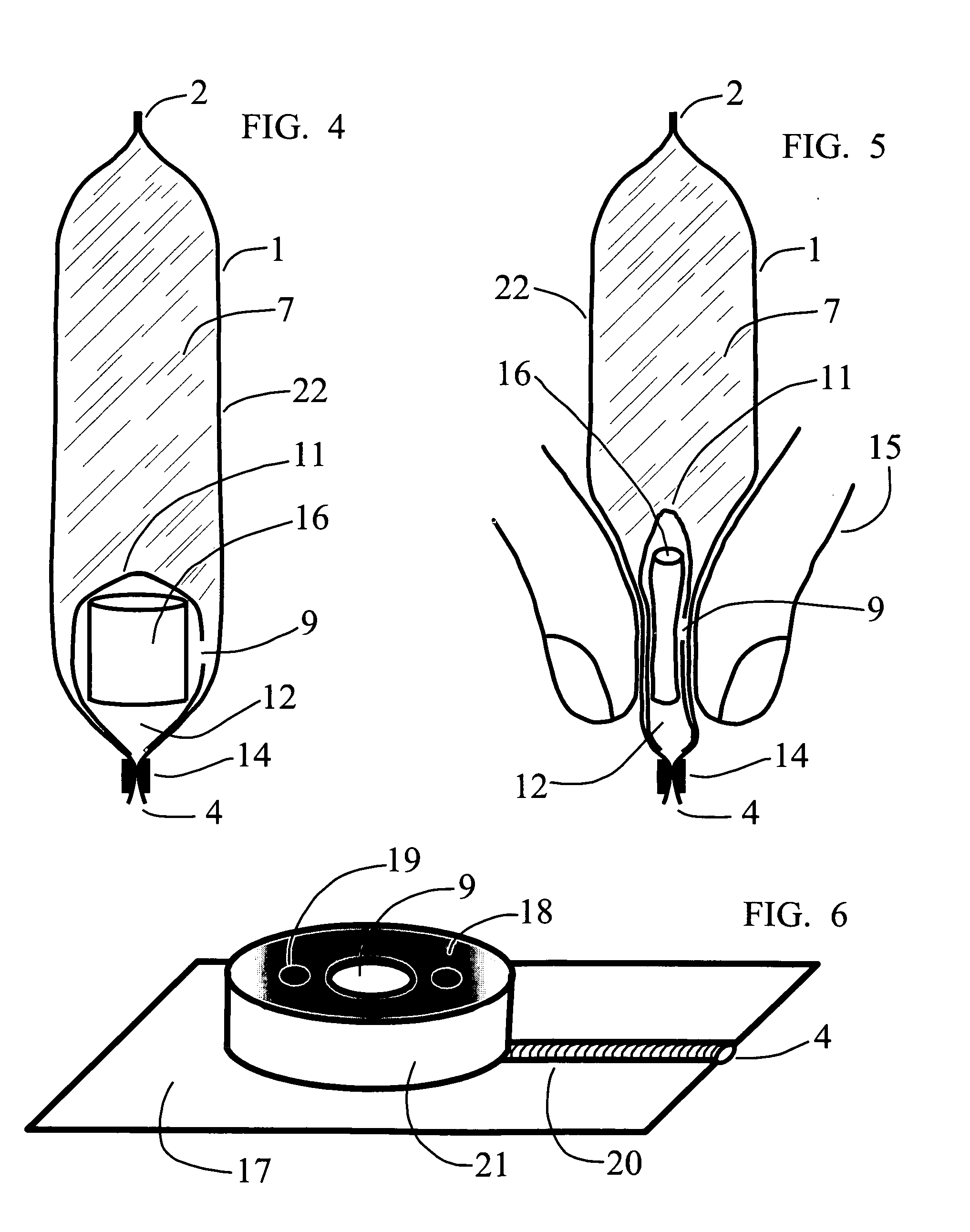
[0027] In FIG. 4 a side view of a fluid dispenser 1 with flexible side walls 22 is illustrated. The front and back walls 22 have boundary seals 2 in the manner of FIG. 1 and define a reservoir chamber 7 containing a liquid product as described in FIG. 2 and FIG. 3. A pump chamber 11 is fully enclosed by the reservoir chamber 7 and separated from that chamber 7 by a flexible pump wall 11. Distinct from the Example 1 embodiment is that here, in this embodiment, the means to maintain and recover the pump chamber 12 volume is not a resilient property and / or construct of the flexible pump wall 11 but an enclosed compressible structure 16 found within the pump chamber 12. The compressible structure 16 can be as simple as a piece of flexible rubber laboratory hose, a more complex polymeric spring construct, or a highly engineered piece of open cell foam. The structure 16 is defined by its purpose which is the capacity to squeezed by external pressure to sufficiently reduce the fluidic volu...

example 3

[0029]FIG. 6 illustrates a form of button pump 18 constructed apart for later inclusion in a reservoir chamber of a fluid dispenser. Shown is a polymeric film base 17 upon which a cylinder or dome 18 of resilient polymer is constructed and sealed to the base 17. An exit channel 20 is formed in the base 17 with a first end opening within the pump chamber formed inside the dome 18 and a second end opening as an exit orifice 4. The dome 18 has an aperture 9 and resilient walls 21 so, when enclosed in a reservoir of liquid product, can behave as a pump in the manner described in Example 1 and Example 2. To position and stabilize the button pump 18 within the reservoir chamber 7 the base 17 edges can be either incorporated in one or more border seal 2 areas or simply attached to a stiff back wall 8. A cuing means, represented here by one or more bumps 19, have been incorporated in the pump surface near the aperture 9 to provide tactile and / or visual guidance to the proper location to whi...


PUM

PropertyMeasurementUnit
flexibleaaaaaaaaaa
volumeaaaaaaaaaa
pressureaaaaaaaaaa

Abstract

A hand operated fluid dispensers comprised of a sealed flexible reservoir chamber containing a fluid, a flexible pump chamber encased by and drawing fluid from the reservoir, and a pump cycled by external pressure applied through a reservoir wall. This class of simple, inexpensive, disposable dispensers is particularly useful in packaging cosmetics, foodstuffs, and healthcare products. As pocketable dispensers they are popular for dispensing small amounts of stored viscous liquids easily damaged when exposure to the atmosphere, a condition where sealed reservoirs coupled with airless pumps working together successfully prevent such product contamination and deterioration. A method of improved healthcare employing such pump dispensers containing a hand sanitizing fluid is also discussed.

Description

FIELD OF THE INVENTION [0001] The present invention relates to hand operated fluid dispensers comprised of a sealed flexible reservoir chamber containing a fluid, a flexible pump chamber encased by and drawing fluid from the reservoir, and a pump cycled by external pressure applied through a reservoir wall. This class of simple, disposable dispensers is particularly useful in packaging cosmetics, foodstuffs, and healthcare products. As pocketable dispensers they are popular for dispensing small amounts of stored viscous liquids easily damaged when exposure to the atmosphere, a condition where sealed reservoirs coupled with airless pumps working together successfully prevent such product contamination and deterioration. BACKGROUND OF THE INVENTION [0002] Dispersement of relatively viscous liquids such as liquid soaps, hand sanitizing fluids, cosmetic creams, insect repellant lotions and similar fluids is often by either squeezable plastic tubes with closable caps or plastic bottles w...

Claims


Application Information

Patent Timeline
Patent Type & Authority Applications(United States)
IPC IPC(8): B65D37/00
CPCA45D34/04A45F5/00A45F2005/006A45F2200/0583A61J1/067B65D77/245B05B11/3032B05B11/3077B05B11/3094B65D75/366B05B11/0043B05B11/026B05B11/1032B05B11/1077B05B11/1094
Inventor HARPER, WILLIAM A.
Owner PENNCREEK
Why Eureka
Try Eureka