
Low temperature fabrication of discrete silicon-containing substrates and devices

a technology of silicon-containing substrates and low-temperature fabrication, which is applied in the direction of semiconductor devices, basic electric elements, electrical equipment, etc., can solve the problems of high manufacturing cost, high energy consumption in the semiconductor industry, and large portion of manufacturing cost from high-temperature and time-consuming processes, so as to achieve cost-effectiveness, less time and money, and further cost-saving

Inactive Publication Date: 2007-11-15
BOARD OF RGT THE UNIV OF TEXAS SYST
View PDF12 Cites 161 Cited by
  • Summary
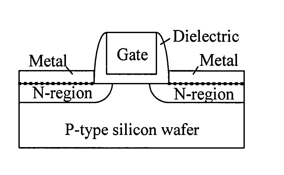
  • Abstract
  • Description
  • Claims
  • Application Information

AI Technical Summary

Benefits of technology

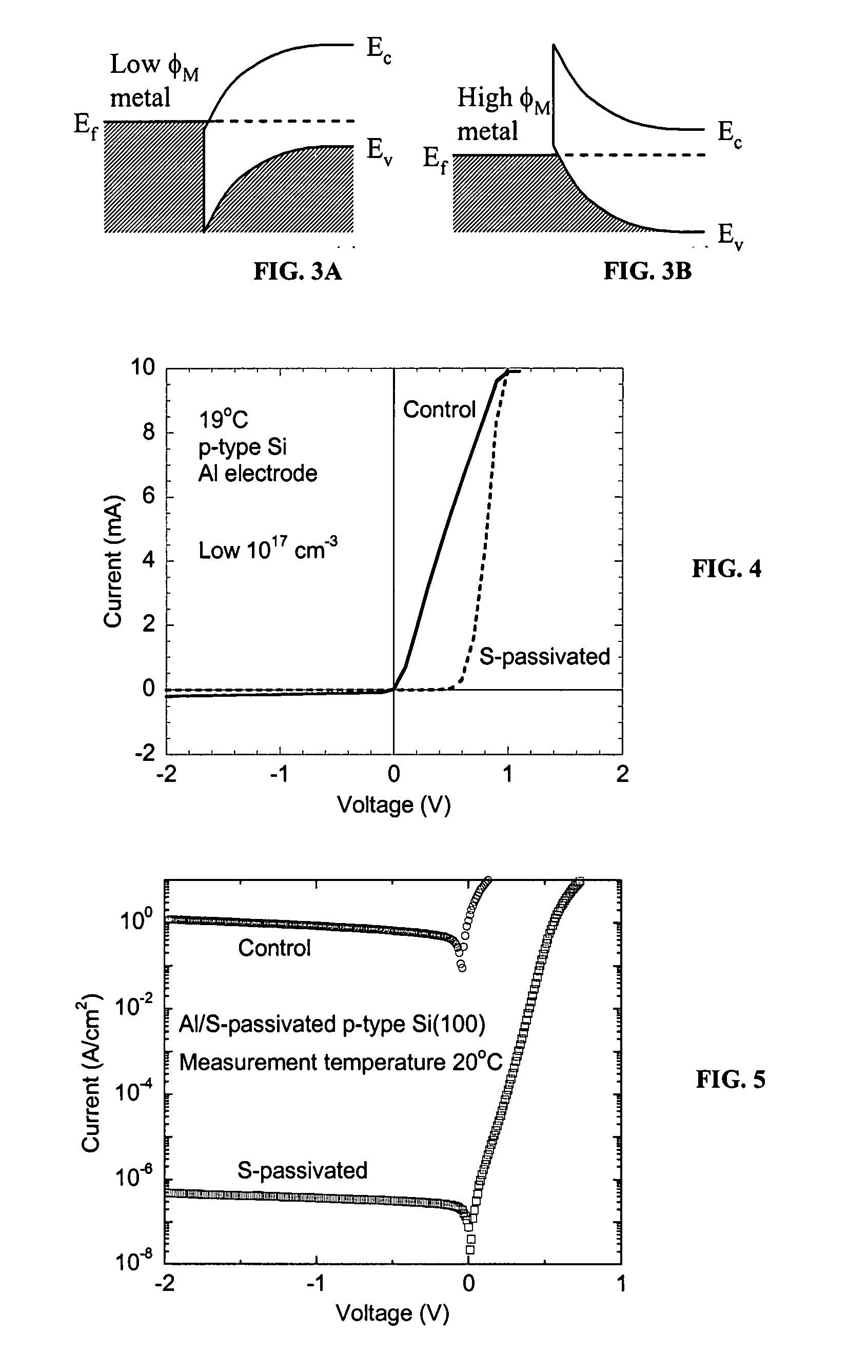
[0006] Fabrication methods and processes described herein occur at a low-temperature and include a passivation process. Fabrication easily incorporates annealing, deposition, patterning, lithography, etching, oxidation, epitaxy and chemical mechanical polishing for forming suitable devices, such as diodes and MOSFETS. Such fabrication is a more cost-effective alternative to a process of diffusion or doping, typical for forming p-n junctions. Whereas diffusion requires temperatures at about 1000° C. for up to several hours, fabrication herein may occur at temperatures below 1000° C., preferably below 700° C. and for less time and money.
[0007] Formation of p-n junctions in discrete silicon diodes and MOSFETs are described herein, fabricated in the absence of diffusion or doping. Formation occurs by incorporating a low temperature passivation process described herein. Formation may be further integrated with other methods, such as low temperature oxidation and low temperature epitaxy to provide further cost and energy savings. Energy consumption is reduced with the low temperature fabrication processes described herein; energy consumption may be reduced as much as two orders of magnitude, as compared with conventional processes.

Problems solved by technology

Energy consumption in the semiconductor industry remains extremely high.
For discrete devices, a large portion of the manufacturing cost comes from high-temperature and time-consuming processes such as diffusion and / or doping.

Method used


Image

  • Low temperature fabrication of discrete silicon-containing substrates and devices
  • Low temperature fabrication of discrete silicon-containing substrates and devices
  • Low temperature fabrication of discrete silicon-containing substrates and devices

Examples


Embodiment Construction

[0021] The invention, as defined by the claims, may be better understood by reference to the following detailed description. The description is meant to be read with reference to the figures contained herein. This detailed description relates to examples of the claimed subject matter for illustrative purposes, and is in no way meant to limit the scope of the invention. The specific aspects and embodiments discussed herein are merely illustrative of ways to make and use the invention, and do not limit the scope of the invention.

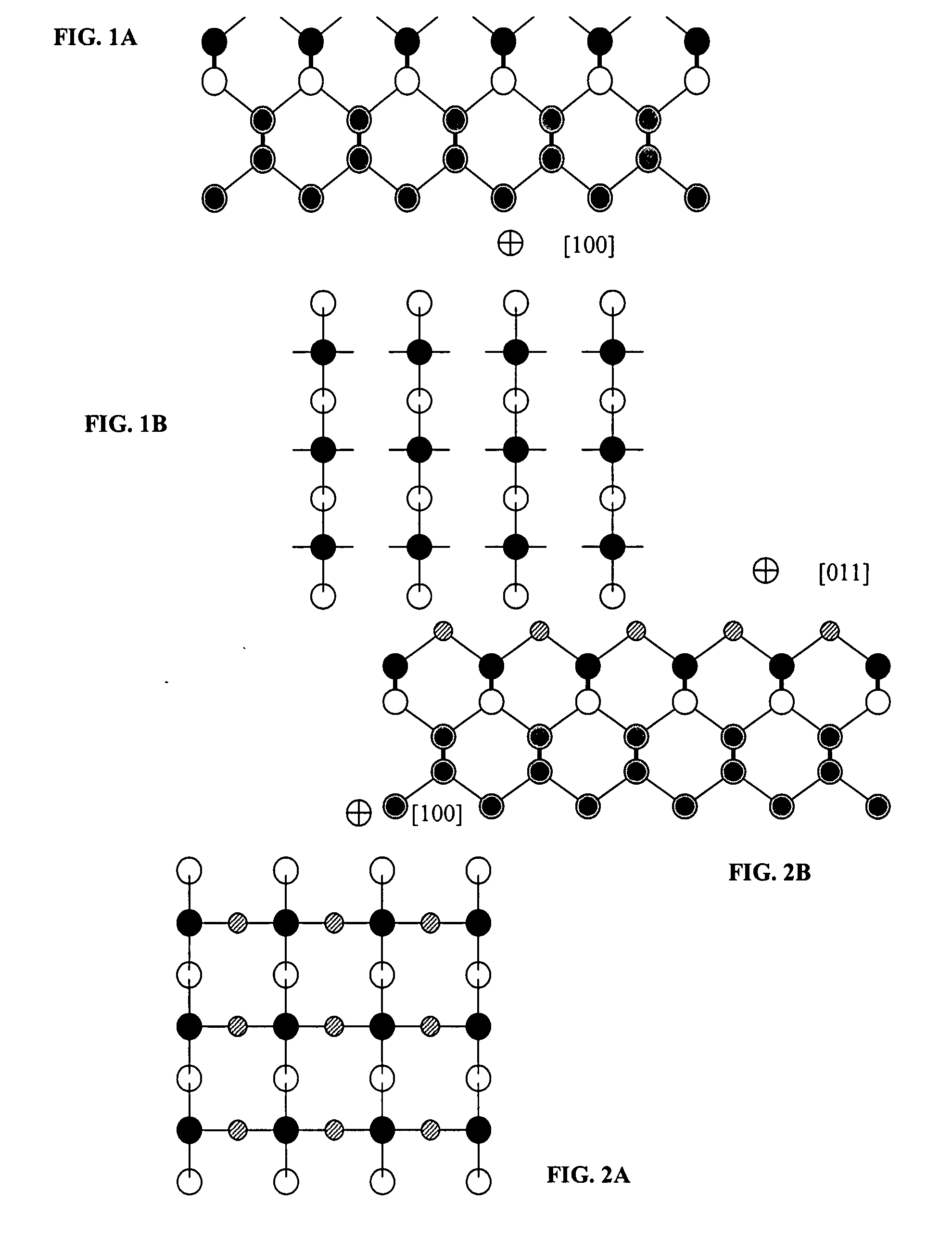
[0022] Dangling bonds and strained bonds are an inherent nature of semiconductor surfaces. Dangling and strained bonds cause a variety of problems in the fabrication of solid-state devices on semiconductor substrates. They are responsible for the high chemical reactivity of the surface by acting as reaction sites for chemical reactions and create surface states that cause the observed properties of electronic devices to vary from their design specifications. ...


PUM


Abstract

Fabrication methods and processes are described, the methods and processes occurring at a low-temperature and involving passivation. The methods and processes easily incorporate annealing, deposition, patterning, lithography, etching, oxidation, epitaxy and chemical mechanical polishing for forming suitable devices, such as diodes and MOSFETs. Such fabrication is a suitable and more cost-effective alternative to a process of diffusion or doping, typical for forming p-n junctions. The process flow does not require temperatures above 700 degrees Centigrade. Formation of p-n junctions in discrete silicon diodes and MOSFETs are also provided, fabricated at low temperatures in the absence of diffusion or doping.

Description

CROSS-REFERENCES TO RELATED APPLICATION [0001] This application is a continuation-in-part of U.S. patent application Ser. No. 11 / 507,223 filed Aug. 21, 2006, which is a continuation-in-part of U.S. patent application Ser. No. 11 / 360,139, filed Feb. 23, 2006, which claims the benefit of Provisional Application No. 60 / 655,383 filed Feb. 23, 2005, and is a continuation in part of U.S. patent application Ser. No. 10 / 822,343 having a filing date of Apr. 12, 2004, which claims the benefit of and is a continuation-in-part of U.S. patent application Ser. No. 10 / 377,015 filed Feb. 28, 2003, now issued as U.S. Pat. No. 6,784,114. Such applications and patents are incorporated herein by reference.STATEMENT REGARDING FEDERALLY SPONSORED RESEARCH OR DEVELOPMENT [0002] The U.S. Government has a paid-up license in this invention and the right in limited circumstances to require the patent owner to license others on reasonable terms as provided for by the terms of Grant Nos. 0322762 and 0620319 awa...

Claims


Application Information

Patent Timeline
IPC IPC(8): H01L29/78H01L21/20H01L21/336
CPCH01L21/76897H01L29/41775H01L29/41783H01L29/7839H01L29/66136H01L29/66545H01L29/66643H01L29/456
Inventor TAO, MENGSHI, FANG
Owner BOARD OF RGT THE UNIV OF TEXAS SYST
Learn More