Structure of Detecting Device Used in Miles System and Gun Simulator

a technology of detecting device and gun simulator, which is applied in the direction of optical radiation measurement, instruments, teaching apparatus, etc., can solve the problems of narrow optical sight angle, inability to receive light, and increase the probability of erroneously determining that the laser light has missed a target, so as to maximize the efficiency of handling equipment

Inactive Publication Date: 2007-11-15
KOREAELECOM
View PDF15 Cites 30 Cited by
  • Summary
  • Abstract
  • Description
  • Claims
  • Application Information

AI Technical Summary

Benefits of technology

[0036] Moreover, the speaker mounted on the simulated magazine in the present invention can substitute wireless installations, thereby maximizing the efficiency of handling the equipment.
[0037] Finally, the present invention improved the problems in the conventiona

Problems solved by technology

Despite its superior characteristics, the conventional detecting element with the above structure has a narrow optical sight angle (α) incapable of receiving light due to an attachment of its optical detector cell to the bottom of its protection case and a resultant narrow detection scope of the detecting elements.
Such problems heighten the probability of erroneously determining that the laser light has missed a target if the laser light hits a side surface of the detecting element or the space between the detecting elements.
However, this measure is not so efficient in terms of cost and management as it requires more detecting elements per soldier or target.
Another problem of the conventional detecting element lies in increase of its entire volume, particularly of its thickness (h), because the optical detector cell and the protection case need to be wrapped by an external skin comprising a filtering window.
This eventually reduces the effect of training.
Another problem of the conventional detecting element lies in its surface, which is a filtering window composed of polycarbonate that is vulnerable to strong impact and frequently malfunctions when soldiers perform severe acts of falling, crawling, ambushing or clashing.
The vacant space between the surface and the internal element fails to protect the thin surface from external import or heavy weight.
Still another problem of t

Method used


Image

  • Structure of Detecting Device Used in Miles System and Gun Simulator
  • Structure of Detecting Device Used in Miles System and Gun Simulator
  • Structure of Detecting Device Used in Miles System and Gun Simulator

Examples


Embodiment Construction

[0073] Best modes for carrying out the present invention will now be described with reference to the accompanying drawings. The matters defined in the description are nothing but the ones provided to assist in a comprehensive understanding of the invention. Thus, it is apparent that the present invention can be carried out without those defined matters. Also, well-known functions or constructions are not described in detail since they would obscure the invention in unnecessary detail.

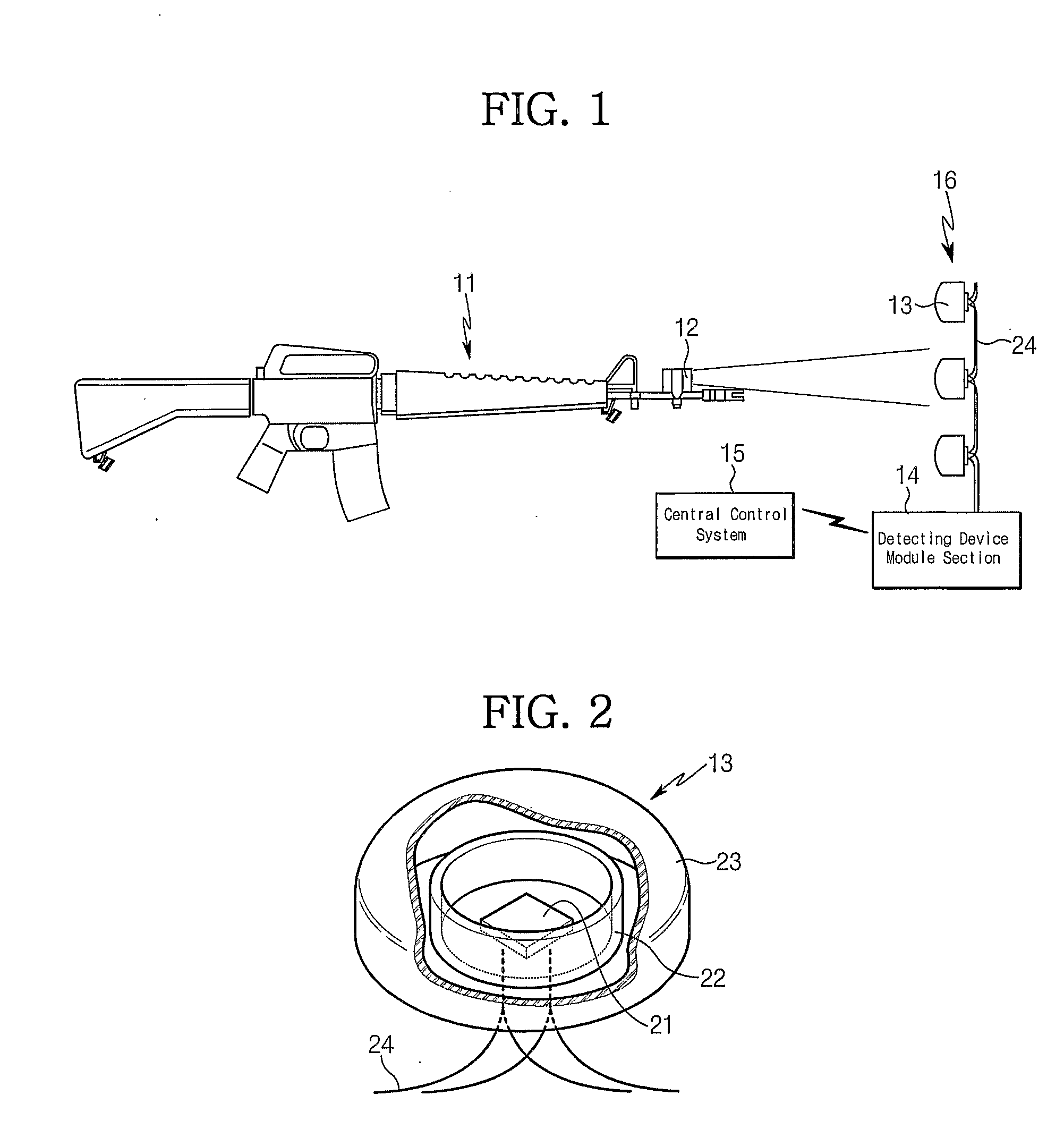
[0074]FIG. 1 is a schematic diagram of a MILES. The MILES as shown in FIG. 1 is operated in the following manner.

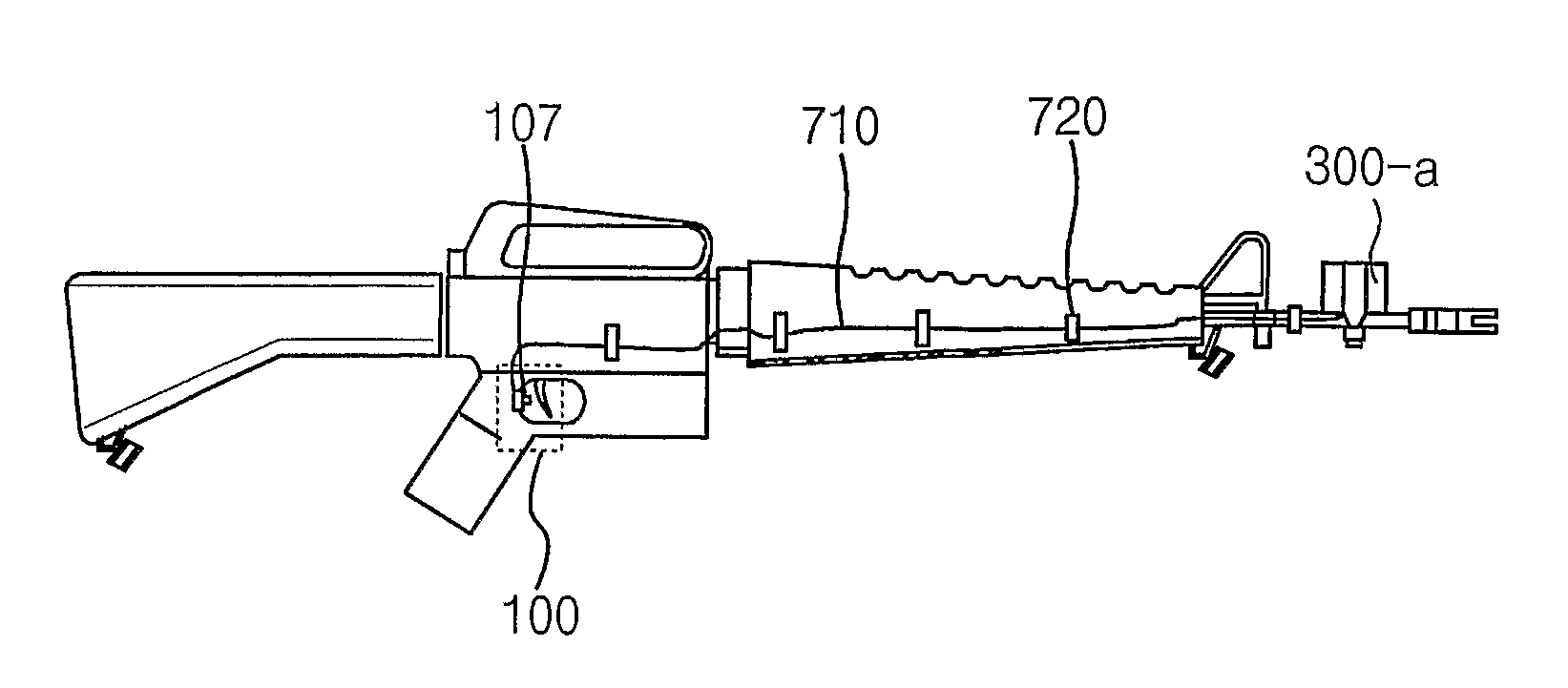
[0075] If a soldier pulls a trigger of individual or public firearms 11 after aiming a target, a blank cartridge, etc. is shot from the firearms 11. At this stage, an acoustic sensor or an optical sensor inside of a SAT 12 senses the sound or light generated at that time and activates an infrared layer laser diode mounted on the SAT 12. Then, the infrared layer laser of a pulse type is shot...


PUM


Abstract

Disclosed is a detecting device for hit determination by detecting a light shot from a transmitter. The detecting device according to the invention comprises a plurality of detecting elements. Each detecting element includes an optical detector cell of a planar shape for generating an electric signal when detecting a light, a protection case of a cylindrical shape for supporting the optical detector cell housed inside thereof, a set of lead wires, each of which being electrically connected to an anode electrode and a cathode electrode of the optical detector cell for supplying the electric signal generated from the optical detector cell to hit determination means, and a protection shield located on a front light detecting surface of the optical detector cell for protecting the optical detector cell from external environment and passing the light. The protection case of a cylindrical shape has an open front surface. The optical detector cell of a planar shape has a light detecting front surface adjacent to the open front surface of the protection case, and a rear surface supported by a packing material packed inside of the protection case. The set of lead wires is elongated from the rear surface of the optical detector cell and protected by the packing material.

Description

TECHNICAL FIELD [0001] The present invention relates to a detecting device used in a MILE system (multiple integrated laser engagement system, hereinafter ‘MILES’) and a gun simulation system, and in particular, to a target detecting device of a MILES using a laser light and to a housing of a magazine shape or a simulated magazine used in an arms transmitter as well as to a gun simulation system related thereto. BACKGROUND ART [0002] During the last several years, military armies have performed training for simulated combat, which is similar to a real combat, by introducing a multiple integrated laser engagement system MILES comprising a small arms transmitter (SAT) for shooting laser light, instead of bullets, which is mounted to small guns or other kinds of arms transmitter, and an optical detector for detecting hit of a target by sensing the laser light. [0003] The conventional detecting element comprises an optical detector cell for converting the detected laser light into elect...

Claims


Application Information

Patent Timeline
IPC IPC(8): F41A33/00G01J1/44F41A33/02F41J5/02
CPCF41A33/02F41G3/2655F41J5/02
Inventor NAMGUNG, BALENTINO
Owner KOREAELECOM
Why Eureka
Try Eureka