Implantable electromagnetic interference tolerant, wired sensors and methods for implementing same

a technology of fault tolerance and electromagnetic interference, applied in the field of fault tolerance sensors, can solve the problems of spurious signals and/or deletion, and achieve the effect of avoiding or positively resolving on

Inactive Publication Date: 2007-11-15
MEDTRONIC INC
View PDF10 Cites 32 Cited by
  • Summary
  • Abstract
  • Description
  • Claims
  • Application Information

AI Technical Summary

Problems solved by technology

As is known, deleterious and / or spurious signals can be generated due exposure of the elongated conductive member to the electromagnetic fields associated with the foregoing sources of interference.

Method used


Image

  • Implantable electromagnetic interference tolerant, wired sensors and methods for implementing same
  • Implantable electromagnetic interference tolerant, wired sensors and methods for implementing same
  • Implantable electromagnetic interference tolerant, wired sensors and methods for implementing same

Examples


Embodiment Construction

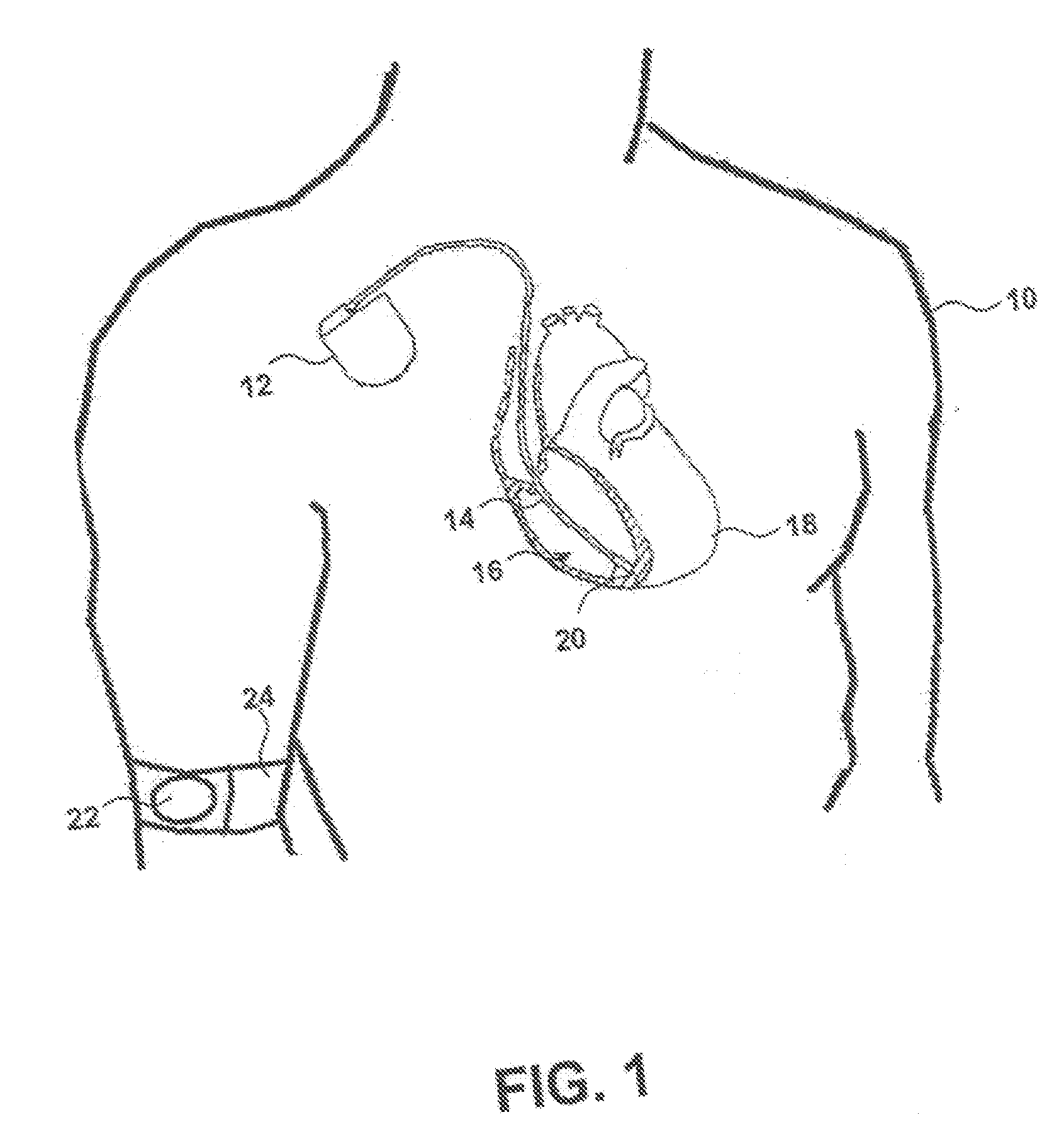
[0026]FIG. 1 is a diagram of a body of a patient 10 having an implantable medical device (AIMD) 12 according to one embodiment of the present invention. As depicted in FIG. 1 lead 14 operatively couples to circuitry (not shown) within the AIMD 12 and extends into the right ventricle 16 of the heart 18. A chronically implantable pressure sensor 20 is shown disposed within a portion of a right ventricle (RV) 16 and couples to lead 14. The pressure sensor 20 monitors and measures changes in blood pressure in the RV 16. The blood pressure in RV 16 is a function of factors such as the volume of RV 16, the pressure exerted by the contraction of heart 18 and the ambient pressure around patient 10 and the blood pressure varies throughout the cardiac cycle as is well known in the art. While a pressure sensor 20 is depicted in FIG. 1 diverse other sensors can directly benefit from the teaching of the present invention as noted hereinabove.

[0027] In one form of the invention the AIMD 12 recei...


PUM


Abstract

The invention addresses possible fault scenarios including exposure to electromagnetic interference (EMI) which can include radio frequency (RF) electromagnetic radiation due to one or more security and / or communication regimens as well as various imaging modalities such as magnetic resonance imaging (MRI), positron electron transmission (PET) imaging or the like. In one aspect, an active implantable medical device (AIMD) is configured to sense a physiologic parameter of a patient and provide a therapy such as cardiac pacing, high-energy cardioversion / defibrillation therapy and / or a drug or substance delivery regimen. An implantable physiologic sensor (IPS) couples to the AIMD with coaxial conductors with the inner conductor carrying the IPS output signals thus avoiding output signal degradation due to EMI. That is, the outer conductor couples to ground providing electromagnetic protection (e.g., like a Faraday cage) to the inner conductive and the output signals.

Description

CROSS REFERENCE AND INCORPORATION BY REFERENCE [0001] This patent disclosure relates to provisional patent application filed on even date hereof; namely, application Ser. No. 60 / 745,789 (Atty Dkt. P-24201.00) entitled, “FAULT TOLERANT SENSORS AND METHODS FOR IMPLEMENTING FAULT TOLERANCE IN IMPLANTABLE MEDICAL DEVICES,” the entire contents, including exhibits appended thereto, are hereby incorporated herein by reference.FIELD OF THE INVENTION [0002] The invention relates generally to fault tolerant sensors and related components that couple to an active implantable medical device (AIMD). BACKGROUND OF THE INVENTION [0003] Implantable medical devices are used to monitor, diagnose, and / or deliver therapies to patients suffering from a variety of conditions. Exemplary AIMDs include implantable pulse generators (IPGs) including pacemakers, gastric, nerve, brain and muscle stimulators, implantable drug pumps, implantable cardioverter-defibrillators (ICDs) and the like. [0004] Due in part ...

Claims


Application Information

Patent Timeline
Patent Type & Authority Applications(United States)
IPC IPC(8): A61N1/18A61N1/00
CPCA61N1/056A61N1/3718A61N1/3702A61N1/36564
Inventor UFFORD, KEITH A.
Owner MEDTRONIC INC
Why Eureka
Try Eureka