

Independent combustion chamber-type internal combustion engine
- Summary
- Abstract
- Description
- Claims
- Application Information
AI Technical Summary
Benefits of technology
Problems solved by technology
Method used
Image

Examples
first embodiment
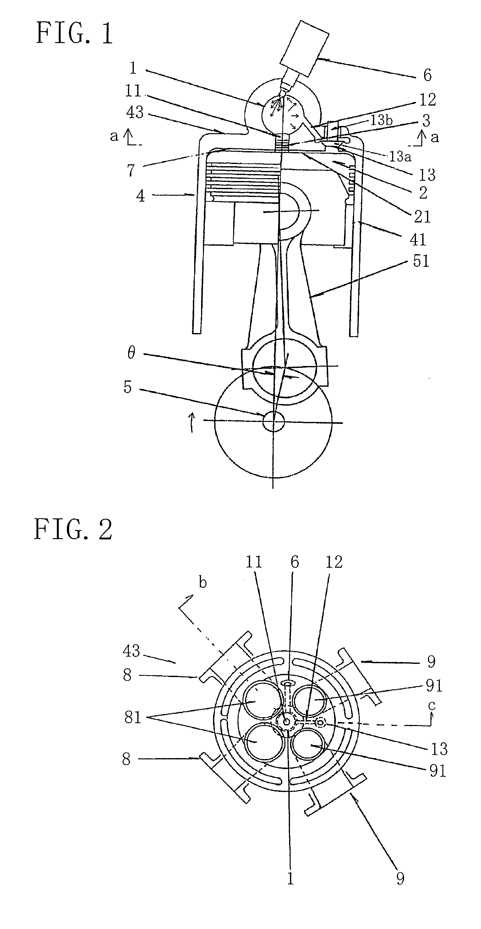
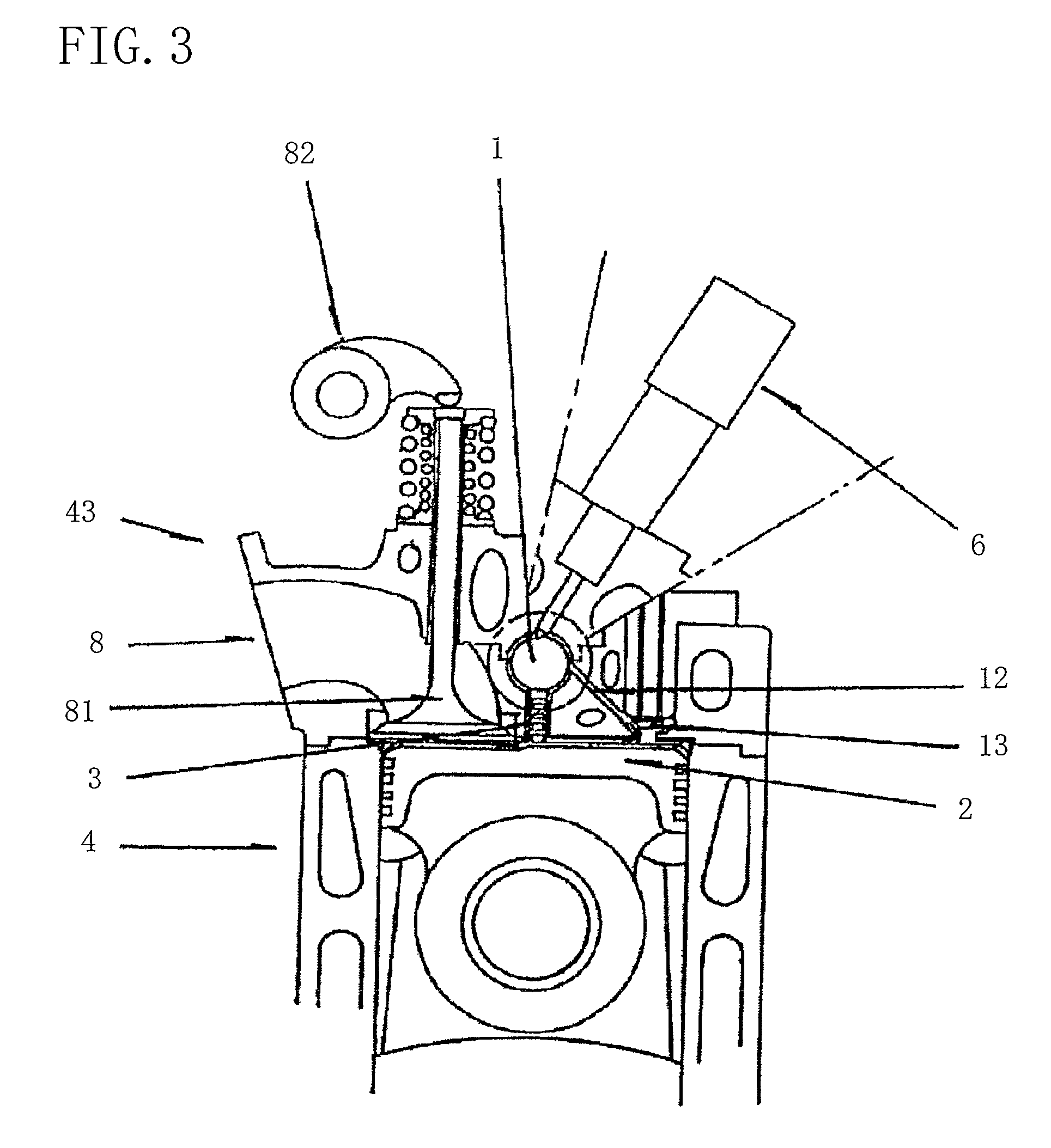
[0045] An independent combustion chamber internal combustion engine of a first embodiment shown in FIGS. 1 and 2 is a so-called reciprocating internal combustion engine in which its suction, compression, explosion, expansion and exhaust strokes are made in an operating chamber 7 of variable volume defined between a housing 4 and a reciprocating piston 2. The internal combustion engine includes an independent combustion chamber 1 provided independently in the housing 4, two communication passages 11 and 12 for communicating the independent combustion chamber 1 with the variable-volume operating chamber 7, and first and second control valves 3 and 13 for controlling the states of communication of the communication passages 11 and 12, respectively.
[0046] The independent combustion chamber 1 is formed in a cylinder head 43 constituting part of the housing 4 and its volume is set, coupled with the volume of the operating chamber 7, to reach a super-high compression ratio much greater th...
second embodiment
[0060] Next, a description is given of a second embodiment of the present invention shown in FIG. 6. The same parts as in the first embodiment and corresponding parts are identified by the same reference numerals and detailed description thereof is not given.
[0061] The independent combustion chamber internal combustion engine according to the second embodiment shown in FIG. 6 is an internal combustion engine in which its suction, compression, explosion, expansion and exhaust strokes are made in an operating chamber 4 of variable volume defined between a housing 4 and a piston 2. The internal combustion engine includes: an independent combustion chamber 1 of fixed volume, formed in the housing 4 and provided with a fuel supply means 6, for independently producing combustion therein; a single communication passage 11 for communicating the independent combustion chamber 1 with the operating chamber 7 of variable volume; and a control valve 3 for allowing introduction of compressed air...
third embodiment
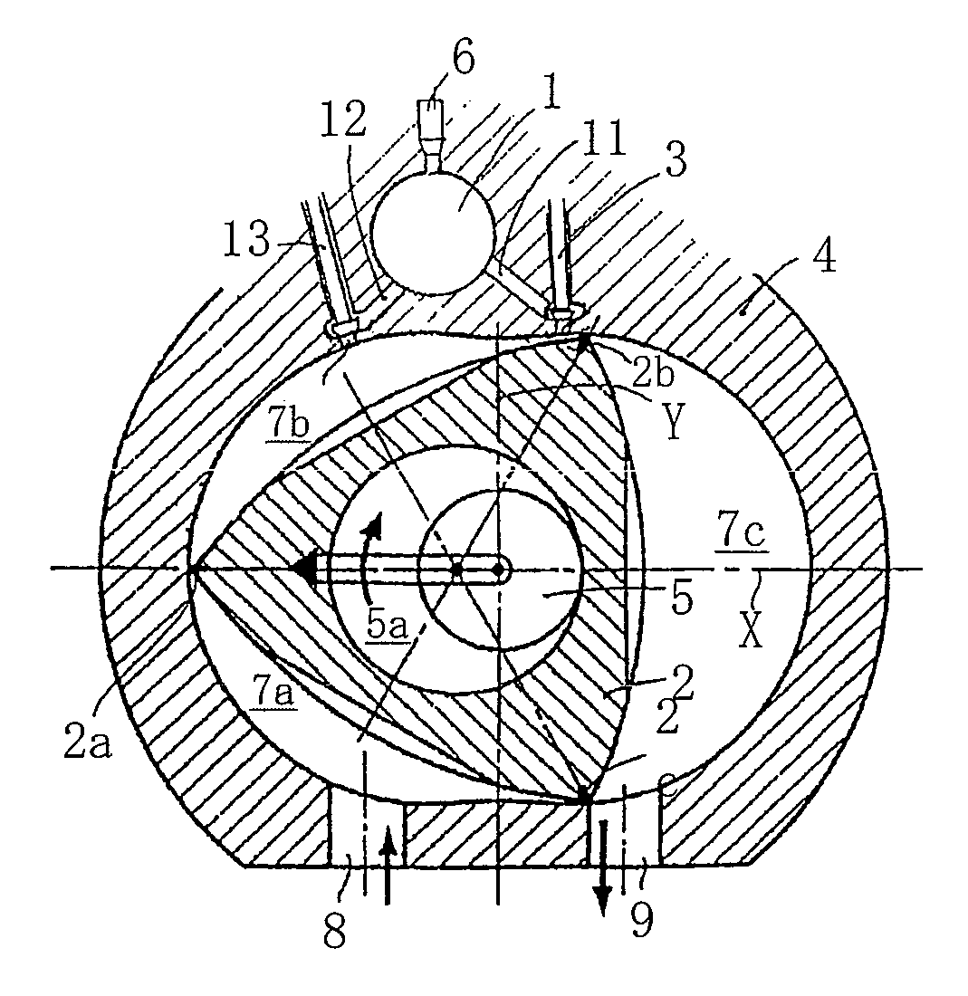
[0064] An independent combustion chamber internal combustion engine according to a third embodiment of the present invention shown in FIGS. 9 to 11 is an application for a rotary internal combustion engine and, as in the first and second embodiments, provides a high-efficiency independent combustion chamber internal combustion engine. FIG. 9 relates to a self-igniting rotary internal combustion engine that is an independent combustion chamber internal combustion engine of the present invention. The rotary internal combustion engine includes a rotor housing 4 having a trochoid inner periphery and a triangular rotor 2 serving as a piston for planetary rotation along the inner periphery of the housing 4.
[0065] Three separated operating chambers 7a, 7b and 7c are defined between the rotor housing 4 and the rotor 2. Each operating chamber changes its volume with the rotation of the rotor 2, initiates air intake from top dead center of the suction stroke, reaches the maximum volume at bo...
PUM
 Abstract
Description
Claims
Application Information