Solar hydrogen generation system

Inactive Publication Date: 2007-12-06
WECHSLER MARK
View PDF16 Cites 38 Cited by
  • Summary
  • Abstract
  • Description
  • Claims
  • Application Information

AI Technical Summary

Benefits of technology

[0007]The present invention overcomes the limitations and problems of the prior art using PV, storage batteries, and electrolyzers in a system that efficiently operates each component at high efficiency. For example, one embodiment of the invention mutually arranges the

Problems solved by technology

While the use of photovoltaic (PV) generated electric power to generate hydrogen is environmentally attractive, this method of producing hydrogen has several problems.
Generally, the electrical characteristics of the PV and electrolyzer are not optimally matched, resulting in either the less-than-optimal use o

Method used


Image

  • Solar hydrogen generation system
  • Solar hydrogen generation system
  • Solar hydrogen generation system

Examples


first embodiment

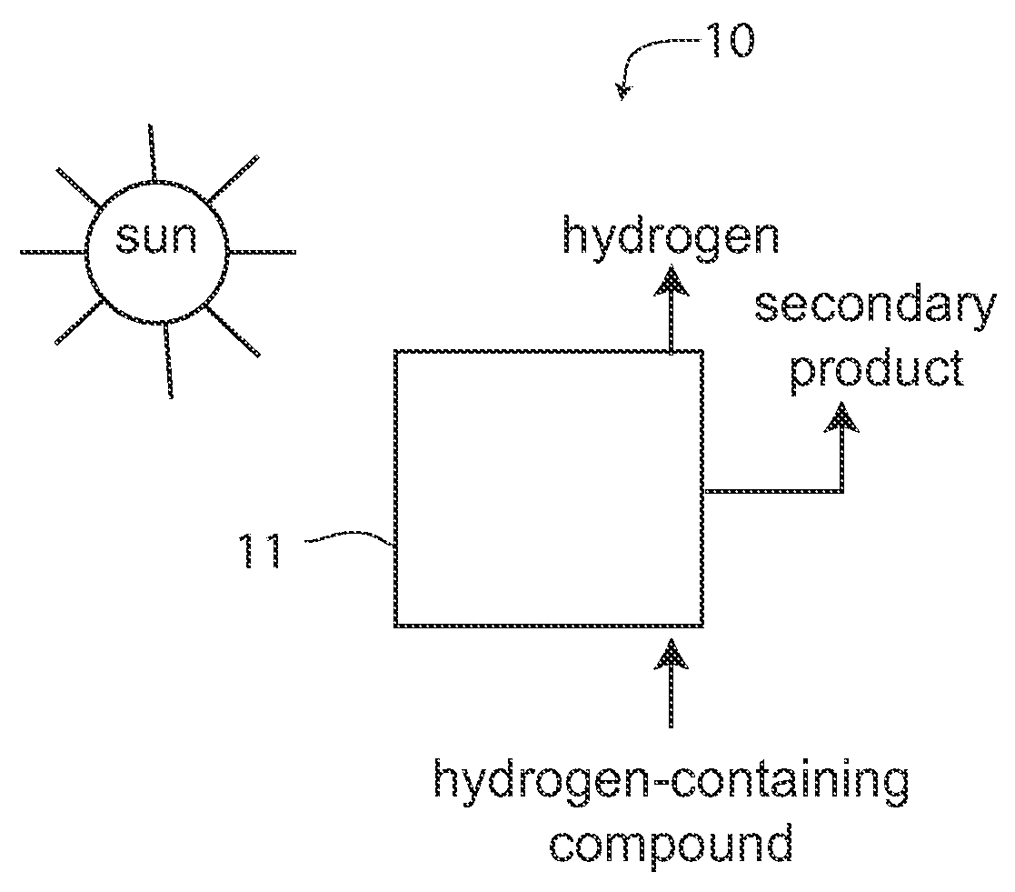
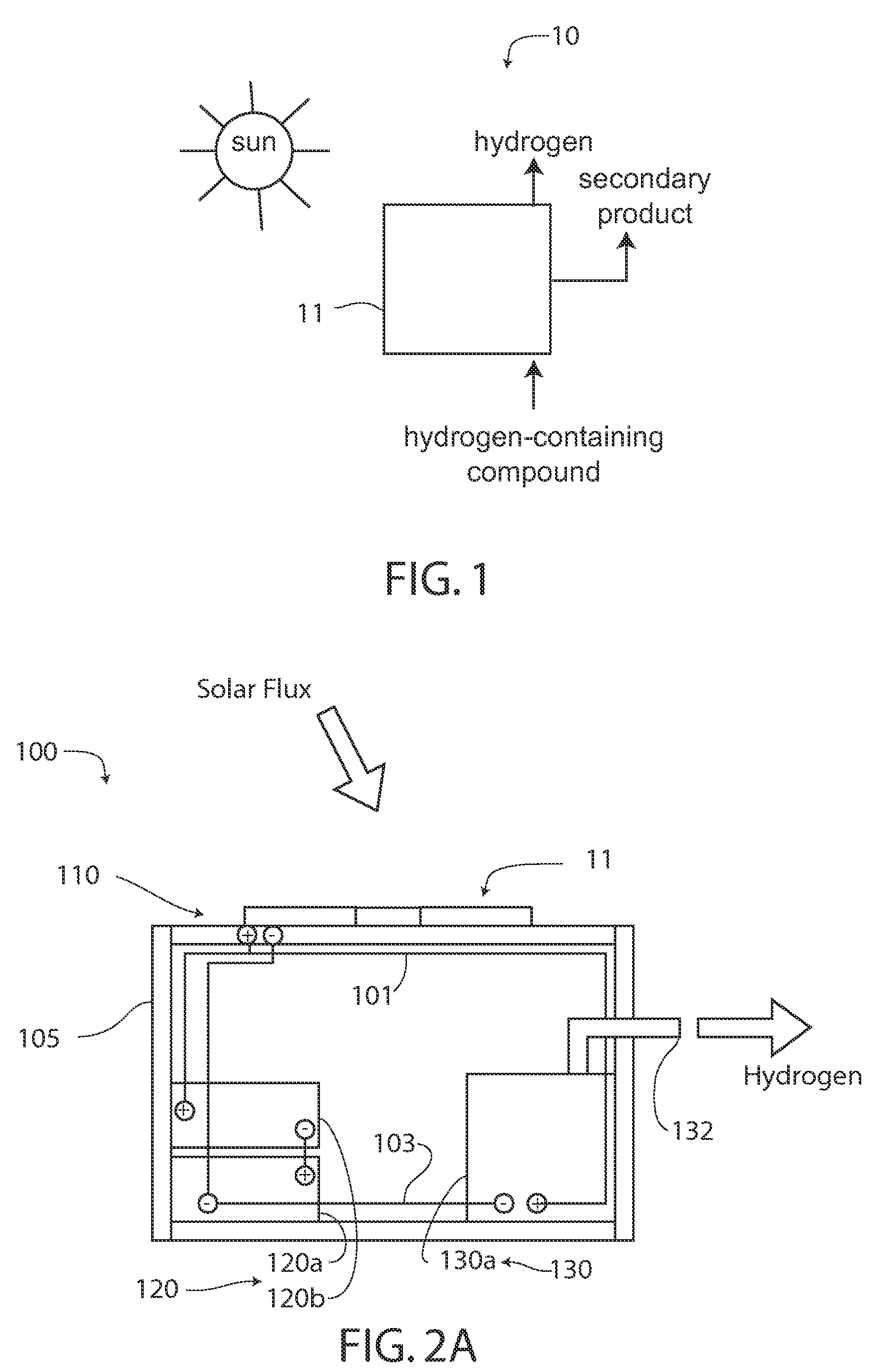
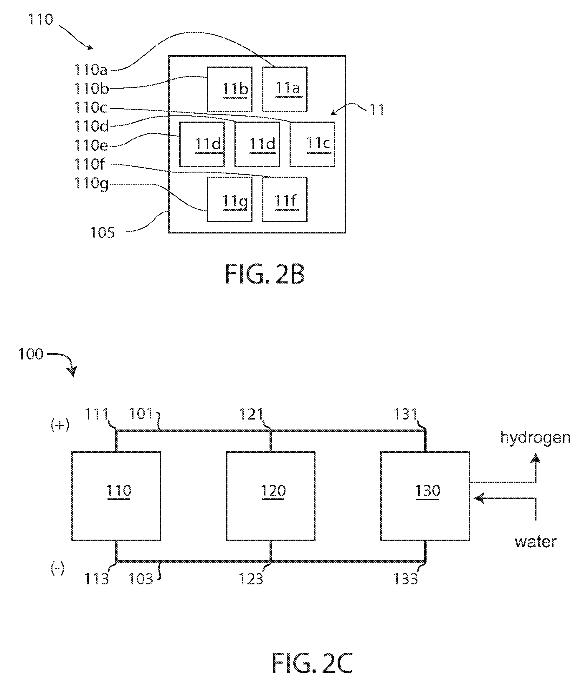
[0034]FIGS. 2A, 2B, and 2C are schematics of a first embodiment solar hydrogen generation system 100, where FIG. 2A is a schematic side view of the solar hydrogen generation system, FIG. 2B is a schematic side view of the system, and FIG. 2C is a schematic wiring diagram of the system. System 100 may be generally similar to the system 10.

[0035]System 100 includes a PV module 110, an electric energy storage module 120, and an electrolyzer module 130. As shown in FIG. 2A, modules 110, 120, and 130 are located on a frame 105. Alternatively, module 110 is located on frame 105 and modules 120 and 130 are located nearby.

[0036]PV module 110 includes, but is not limited to, one or more solar energy-to-electricity generating devices formed of bulk, thin film, multi-layered thin-film composites, polymers, or matrices thin-film photovoltaic materials in a conductive polymers or mesoporous metal oxide matrix, and referred to herein without limitation as “PV devices.” PV modules that may be used...

second embodiment

[0042]FIG. 3 is a schematic of a second embodiment solar hydrogen generation system 300, which may be generally similar to systems 10 or 100, except as described below.

[0043]System 300 includes magnifying optics—specifically a lens 301 positioned above PV module 110 using frame 303, which is otherwise similar to frame 105. The design on magnifying optics is well known in the field. As an example which is not meant to limit the scope of the present invention, if lens 301 has a focal length, f, and is positioned a distance, L, above PV module 110, then the magnification, M, is given by M=f / (f−L). This magnification is also referred to herein as the number of “suns”—that is a magnification of 2 is the equivalent to “2 suns” of flux. Alternatively, compound lenses or non-imaging optical devices are used to magnify the solar flux on PV module 110.

third embodiment

[0044]FIG. 4 is a schematic of a third embodiment solar hydrogen generation system 400, which may be generally similar to the systems 10, 100, or 300, except as described below.

[0045]System 400 includes a frame 401 on which PV module 110 is mounted and, alternatively, a lens 301. System 400 also includes a tracking system 410 that includes an electronic device 411 mounted on a frame 401, a motor / gimbal assembly 413, and a mounting post 415 that is mounted in the ground. Electric energy storage modules 120 and electrolyzer module 130 are located on the ground near mounting post 415. FIG. 4 also schematically shows the wiring of modules 110, 120, and 130.

[0046]The mounting of PV on trackers is well known in the art. Typically the PV is rotatably mounted to present surface 11 towards the sun by rotating system 400 using one or more motors. Thus, for example, photovoltaic module 110 is driven by motor / gimbal assembly 413 such that surface 11 is pointed towards the sun. By tracking the s...


PUM


Abstract

A solar hydrogen generation system is disclosed that efficiently utilizes photovoltaic cells, storage batteries, and electrolyzers to generate hydrogen from the sun by direct coupling of these components. The system mutually arranges the photovoltaic cells, batteries, and electrolyzers in series, and the series components in parallel. The arrangement allows the voltages of the photovoltaic cells, batteries, and electrolyzers to match each other for optimal performance. The invention further provides for continuous hydrogen generation, even through the night or periods of low solar flux, and a system for preventing the overcharging of the batteries.

Description

BACKGROUND OF THE INVENTION[0001]1. Field of the Invention[0002]The present invention generally relates to systems for generating hydrogen using solar energy, and more particularly to apparatus and methods for generating hydrogen using solar energy.[0003]2. Discussion of the Background[0004]As the world's oil reserves are diminishing and energy demand increases, there is an ongoing effort to develop alternative energy sources. Hydrogen plays a key role in that it is an energy carrier that can be generated using many different methods including, but not limited to, reforming of hydrocarbon fuels, such as by steam reforming, biological activity using specially tailored microorganisms, and the electrolyzing of water. Electrolysis is an electrically driven process that liberates the hydrogen stored in water. The electricity for electrolysis typically comes from conventionally obtained, grid power.[0005]An alternative method of producing hydrogen is through a solar electric driven electr...

Claims


Application Information

Patent Timeline
IPC IPC(8): H02N6/00
CPCC25B15/00H01L31/0543H02S40/38Y02E10/52Y02E70/30Y02P20/133
Inventor WECHSLER, MARK
Owner WECHSLER MARK
Why Eureka
Try Eureka