Hub Unit for Driving Wheel
a technology of a hub unit and a driving wheel, which is applied in the direction of mechanical equipment, instruments, transportation and packaging, etc., can solve the problems of troublesome assembly and adjustment process, difficult to mount the sensor, and troublesome arrangement of the harness which is extended from the sensor or to prevent, so as to save manufacturing costs and simplify the form , the effect of the length of the sensor
- Summary
- Abstract
- Description
- Claims
- Application Information
AI Technical Summary
Benefits of technology
Problems solved by technology
Method used
Image

Examples
first embodiment
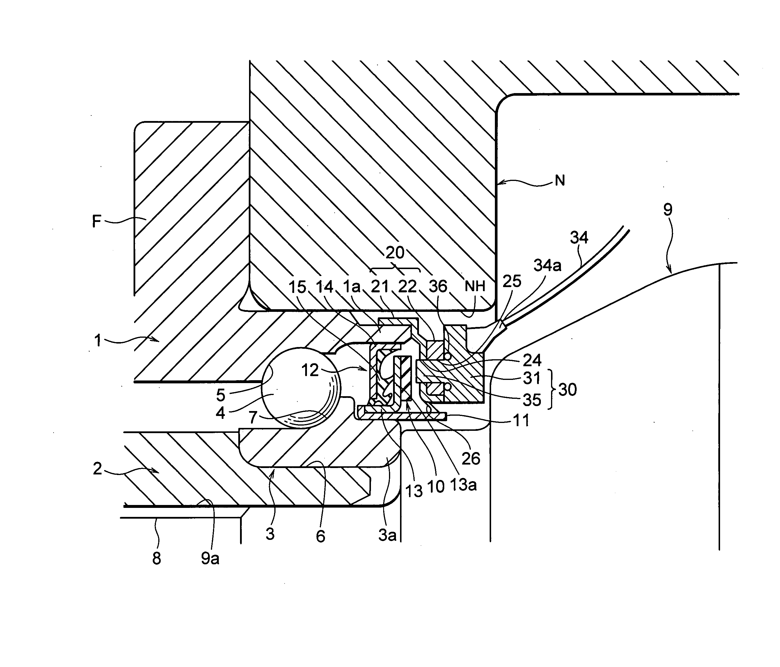
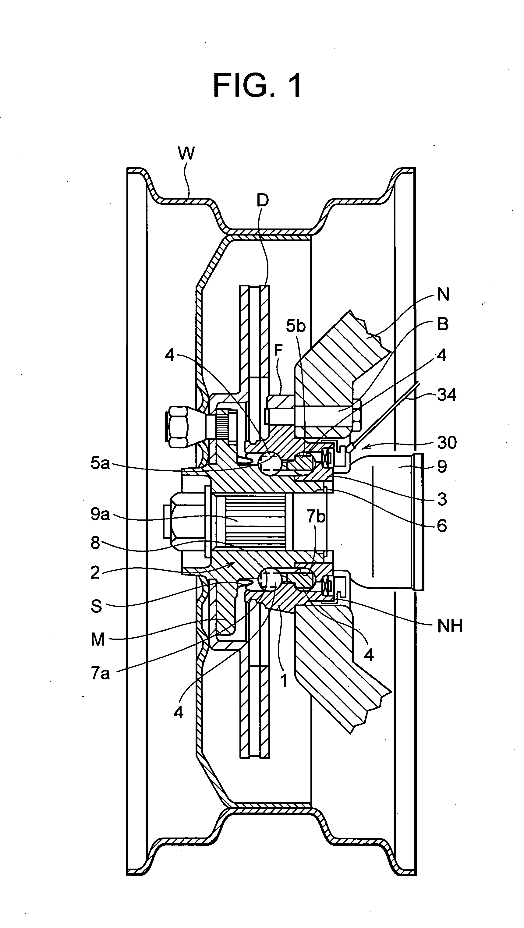
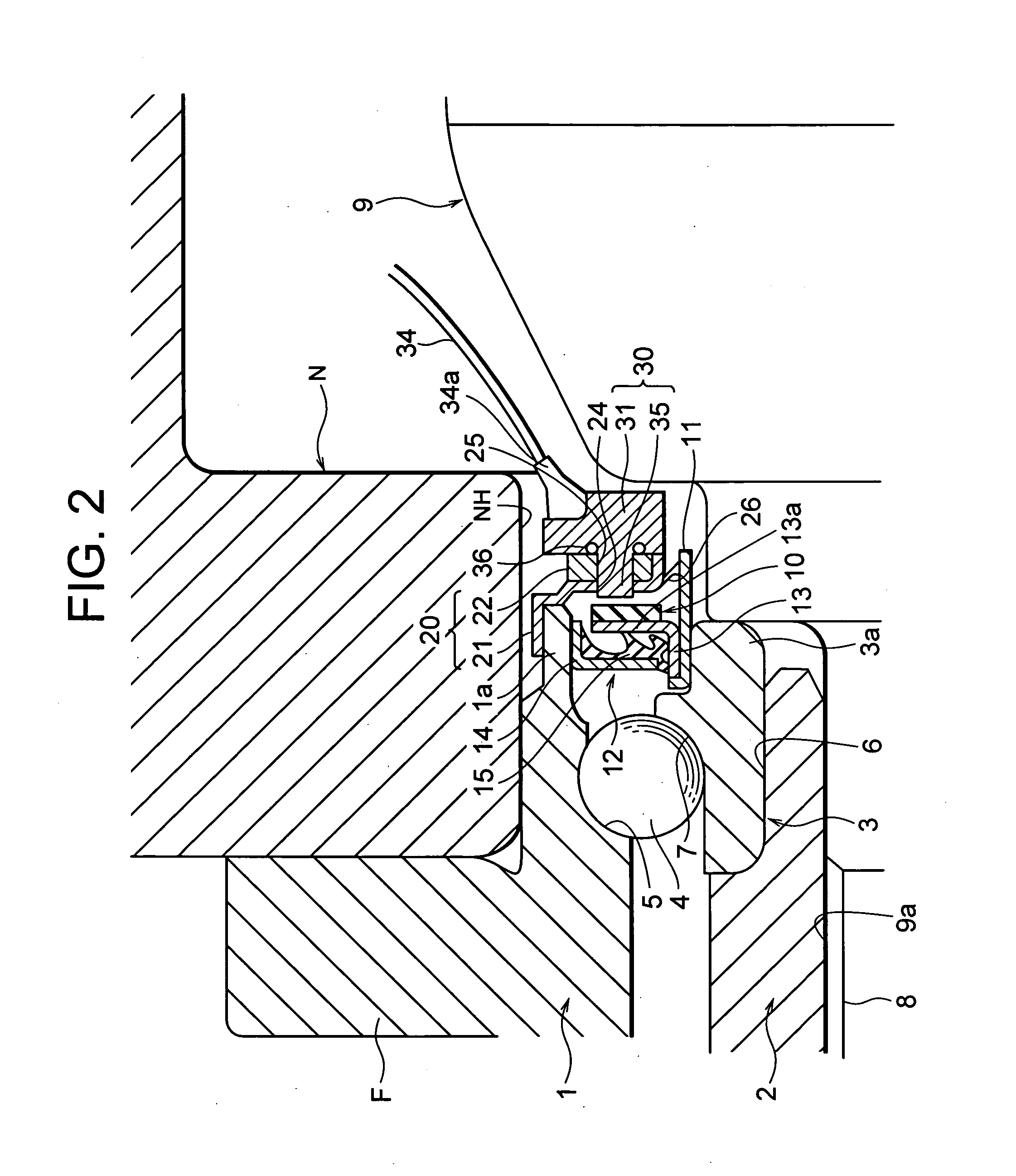
[0110]FIG. 2 is an enlarged sectional view showing an essential part of the hub unit for a driving wheel according to the first embodiment of the present invention and shown in FIG. 1. FIG. 3 is a side view of a sensor for detecting a speed of rotation shown in FIG. 2.
[0111] In the first embodiment, on the inner side in the car width direction of the inner ring 3 (on the right side in FIG. 2), there is provided a magnetic encoder 10. This magnetic encoder 10 is formed to be disc-like, and is alternately magnetized to have a plurality of north poles and south poles in the circumferential direction thereof.
[0112] Note that the magnetic encoder can be formed of rubber, resin, or the like.
[0113] The magnetic encoder 10 is attached to a cylindrical member 11 which is fixed to an inner end portion 3a of the inner ring 3 in the car width direction through a seal member 12.
[0114] The seal member 12 comprises a cylindrical core metal member 13 which is secured to the cylindrical member 1...
second embodiment
[0137]FIG. 5 is a schematic view showing an internal structure of a sensor for detecting a speed of rotation according to a second embodiment of the present invention.
[0138] In the second embodiment, the electronic components a, b, c, . . . , of the sensor accommodated in the sensor main body 31 (cap) formed circumferentially are disposed along the circumferential form of this cap. In addition, these electronic components a, b, c, . . . , are connected to the harness 34 (code or connector).
[0139] As described above, according to the present embodiment, the internal circuit of the sensor 30 for detecting a speed of rotation is disposed circumferentially in the sensor main body 31 (cap), which resultantly contributes to reduce the size and the weight of the knuckle N and also to enhance the strength thereof. It is also possible to effectively utilize a vacant space on the circumference, which can contribute to reduce the size of the hub unit incorporated in the sensor.
(Variation o...
third embodiment
[0143]FIG. 7 is a sectional view of an essential part of the hub unit for a driving wheel according to a third embodiment of the present invention, and FIG. 8 is a perspective view of the knuckle shown in FIG. 7.
[0144] The basic structure of the third embodiment is substantially the same as that of the foregoing first embodiment, so that only different points will be described.
[0145] The sensor holder 20 is constituted only by the core metal member 21, and this core metal member 21 is constituted by a cylindrical portion which is fixedly fitted on an inner end portion 1a of the outer ring 1 in the car width direction and a portion with a substantially U-shaped section which is extended inwardly in the radial direction from the inner end of the cylindrical portion to surround and retain the sensor main body 31 of the sensor 30 for detecting a speed of rotation from the inner side in the car width direction.
[0146] The hub unit mounting hole NH of the knuckle N is formed with an axi...
PUM
 Abstract
Description
Claims
Application Information
 - R&D
- Intellectual Property
- Life Sciences
- Materials
- Tech Scout
- Unparalleled Data Quality
- Higher Quality Content
- 60% Fewer Hallucinations
Browse by: Latest US Patents, China's latest patents, Technical Efficacy Thesaurus, Application Domain, Technology Topic, Popular Technical Reports.
© 2025 PatSnap. All rights reserved.Legal|Privacy policy|Modern Slavery Act Transparency Statement|Sitemap|About US| Contact US: help@patsnap.com