Sensor array for perimeter defense

Active Publication Date: 2007-12-06
LITTON SYST INC +1
View PDF4 Cites 12 Cited by
  • Summary
  • Abstract
  • Description
  • Claims
  • Application Information

AI Technical Summary

Problems solved by technology

Current perimeter defense systems utilizing optical fiber are limited in the feedback they provide the user.
Most only offer a solution that an intrusion has occurred and localization is not particularly accurate.
Additionally, there is no means to track and identify the intrusion as to what type an object it is.
There are also problems with these current devices as the discrimination between environmental conditions (wind, rain, etc.) is poor and triggers a false alarm dispatching security forces unnecessarily.

Method used


Image

  • Sensor array for perimeter defense
  • Sensor array for perimeter defense
  • Sensor array for perimeter defense

Examples


Embodiment Construction

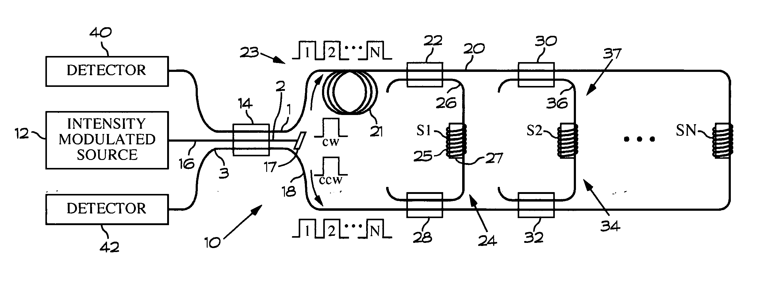
[0009] Referring to FIG. 1, a sensor array 10 includes an intensity modulated optical signal source 12 whose output is input to a 3×3 optical coupler 14 via an optical fiber 16. The optical coupler 14 splits the signal equally among its three output ports 1-3 and forms a clockwise (cw) pulse and a counter clockwise (ccw) pulse that propagate in an optical fiber loop 18 that is connected to the output ports 1 and 3 of the optical coupler 14. Light that remains in the optical fiber 16 after passing through the coupler 14 is absorbed by a light absorber 17.

[0010] The optical fiber loop 18 serves as a telemetry bus 20. The cw pulse travels along the telemetry bus 20 through a delay coil 21 formed therein to a bus coupler 22 that splits off a portion of the light in the cw pulse directs it to a sensor rung 24 via an optical fiber 26. The sensor rung 24 includes a first sensor S1 that in the illustrated embodiment is preferably a hydrophone. The sensor S1 may be formed by wrapping a coil...


PUM


Abstract

An intensity modulated broadband optical signal source is arranged to produce optical signals in a plurality of wavelength bands. A demultiplexer / multiplexer pair receives optical signals from the optical signal source and produces a separate optical signal for each wavelength band. An optical coupler is arranged to receive the separate optical signals. Optical fiber loops connected to the optical coupler guides both clockwise and counter clockwise waves for each of the separate optical signals. The optical signals propagate through a sensor in each loop and then combine in the optical coupler to form a plurality of interference signals in each wavelength band. A multiplexer is optically coupled to the optical coupler to receive the interference signals therefrom, and a detector array having a selected detector corresponding to the each of the plurality of wavelength bands is arranged to provide an electrical signal that indicates the interference signals for each wavelength band.

Description

BACKGROUND OF THE INVENTION [0001] This invention relates generally to fiber optic sensors and particularly to a fiber optic sensor array arranged for identifying and tracking an intrusion into a defined region. [0002] Current perimeter defense systems utilizing optical fiber are limited in the feedback they provide the user. Most only offer a solution that an intrusion has occurred and localization is not particularly accurate. Additionally, there is no means to track and identify the intrusion as to what type an object it is. There are also problems with these current devices as the discrimination between environmental conditions (wind, rain, etc.) is poor and triggers a false alarm dispatching security forces unnecessarily. SUMMARY OF THE INVENTION [0003] A perimeter defense system according to the present invention comprises an intensity modulated broadband optical signal source arranged to produce optical signals in a plurality of wavelength bands and a demultiplexer / multiplexe...

Claims


Application Information

Patent Timeline
IPC IPC(8): H04J14/02
CPCG01D5/35383
Inventor MEYER, A. DOUGLAS
Owner LITTON SYST INC
Why Eureka
Try Eureka