Water treatment system

Inactive Publication Date: 2007-12-13
OXYGENATOR WATER TECH
View PDF26 Cites 13 Cited by
  • Summary
  • Abstract
  • Description
  • Claims
  • Application Information

AI Technical Summary

Benefits of technology

[0009]The present invention provides one or a plurality of emitters contained in one or a plurality of electrolysis chambers through which water flows. When activated, the emitters cause the evolution of microbubbles of oxygen. The emitters are connected to a power source controlled by a controller containing a flow switch. When the flow switch senses water demand, that is, when a spigot is opened, the controller causes voltage to be applied to the electrolysis cells. The electrolysis cell or cells comprise electrodes separated from each other by a critical distance as more fully described in co-pending patent application Ser. No. 10/732,326 (the “'326” application), the teachings of which are incorporated

Problems solved by technology

Water for domestic, industrial and farm use frequently is contaminated with minerals, organic substances, and bacteria that render the water unpotable and even dangerous to health.
Among these contaminants is ferrous iron, which forms a colloidal mass with water and fouls plumbing.
Chlorine is not totally harmless.
For those small municipalities or individual farms or homes, it is impractical to use chlorine to treat w

Method used


Image

  • Water treatment system
  • Water treatment system
  • Water treatment system

Examples


example 1

Experimental Model

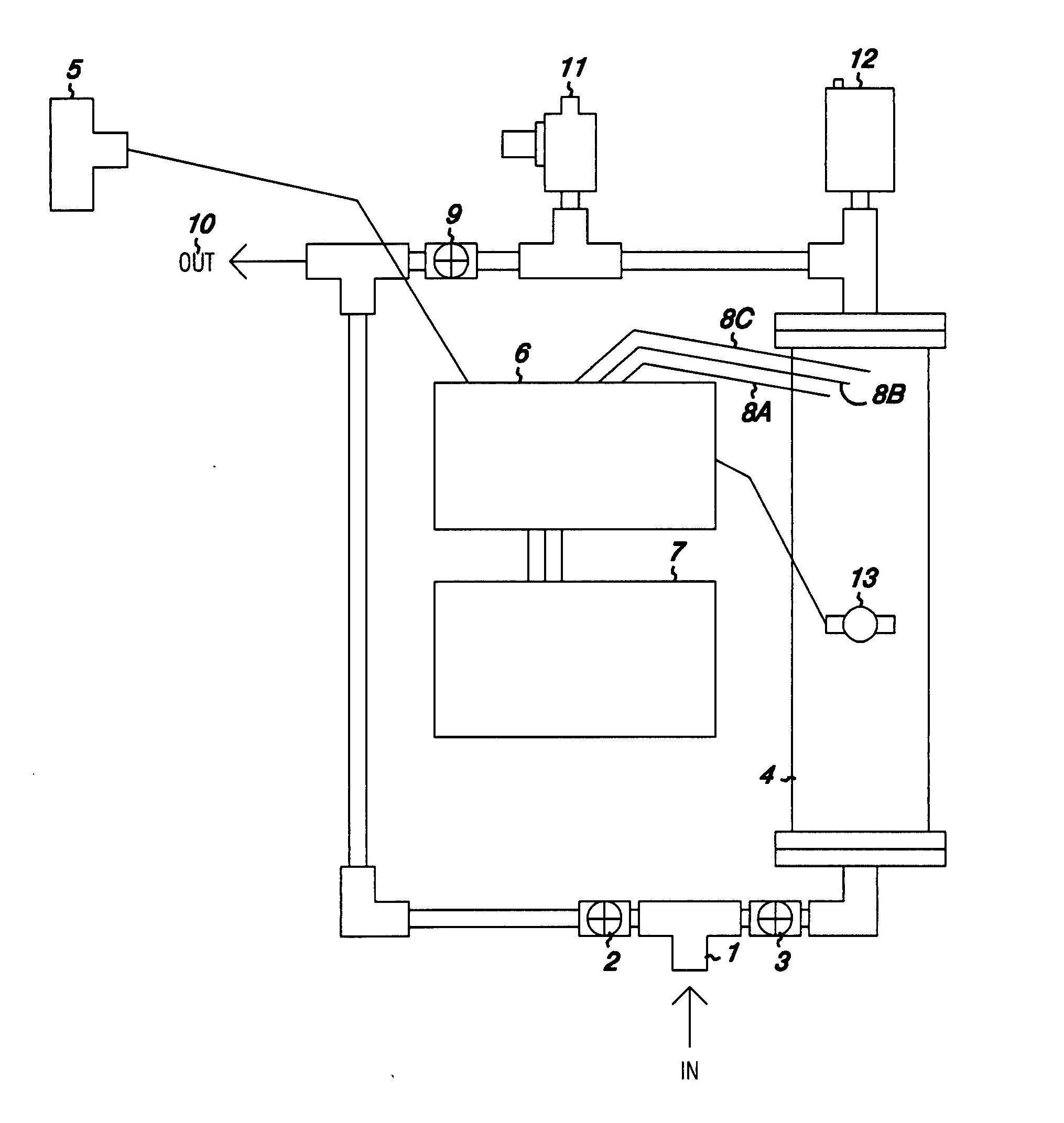
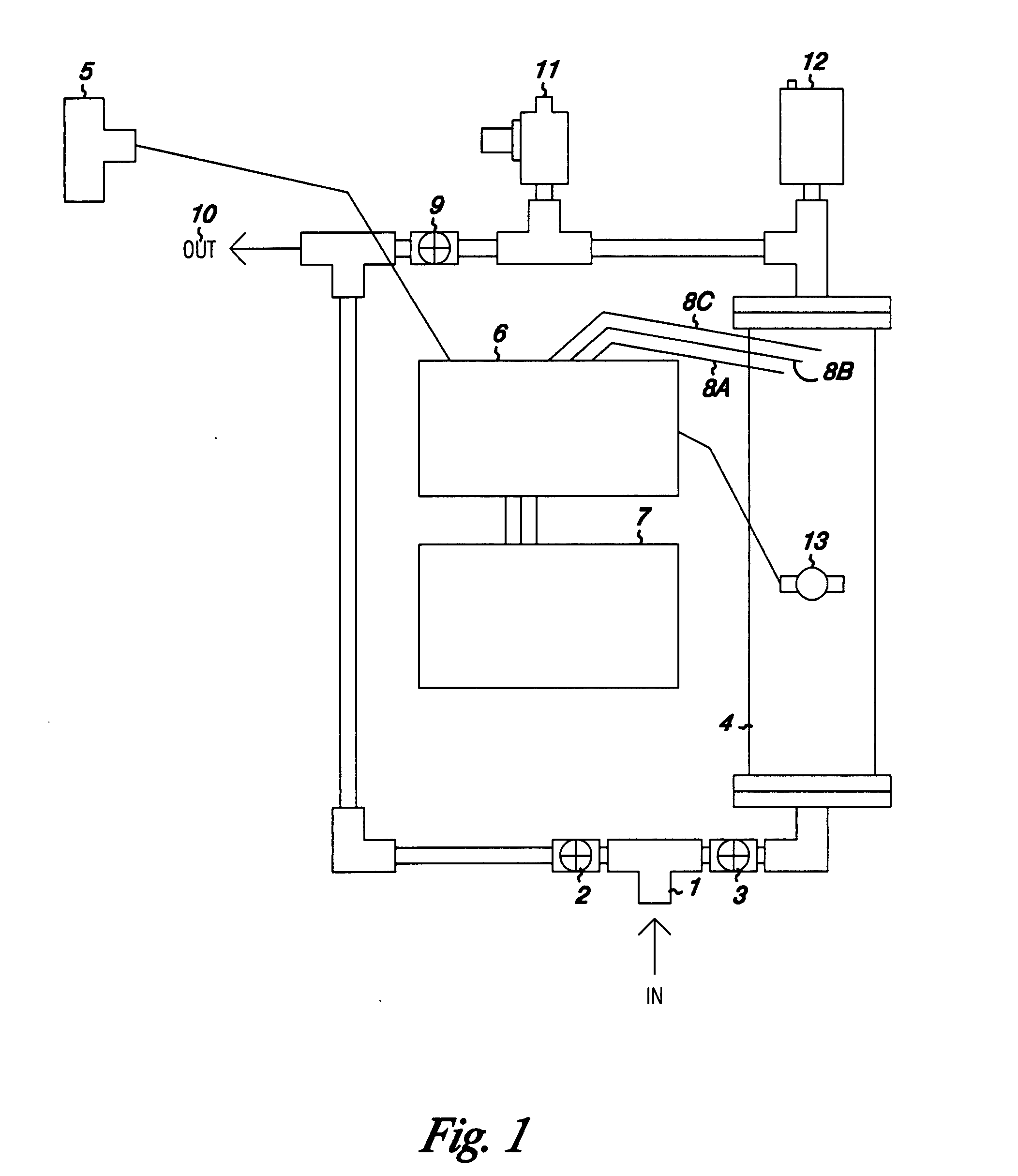
[0026]Turning to FIG. 1, the intake 1 is attached to the water supply to be treated. Valve 2 is shut; valve 3 is open to allow water into the electrolysis chamber 4. When the flow switch 5 connected to the controller 6 senses the water flow, the power supply 7 supplies voltage to the plates 8a, 8b and 8c, causing oxygen to be evolved. The oxygenated water passes valve 9 to exit by the outlet 10. Water pressure relief valve 11 and gas relief valve 12 will relieve pressure in the system. When the temperature sensor 13 senses an increase in temperature, the controller 6 inactivates the plates 8a, 8b and 8c.

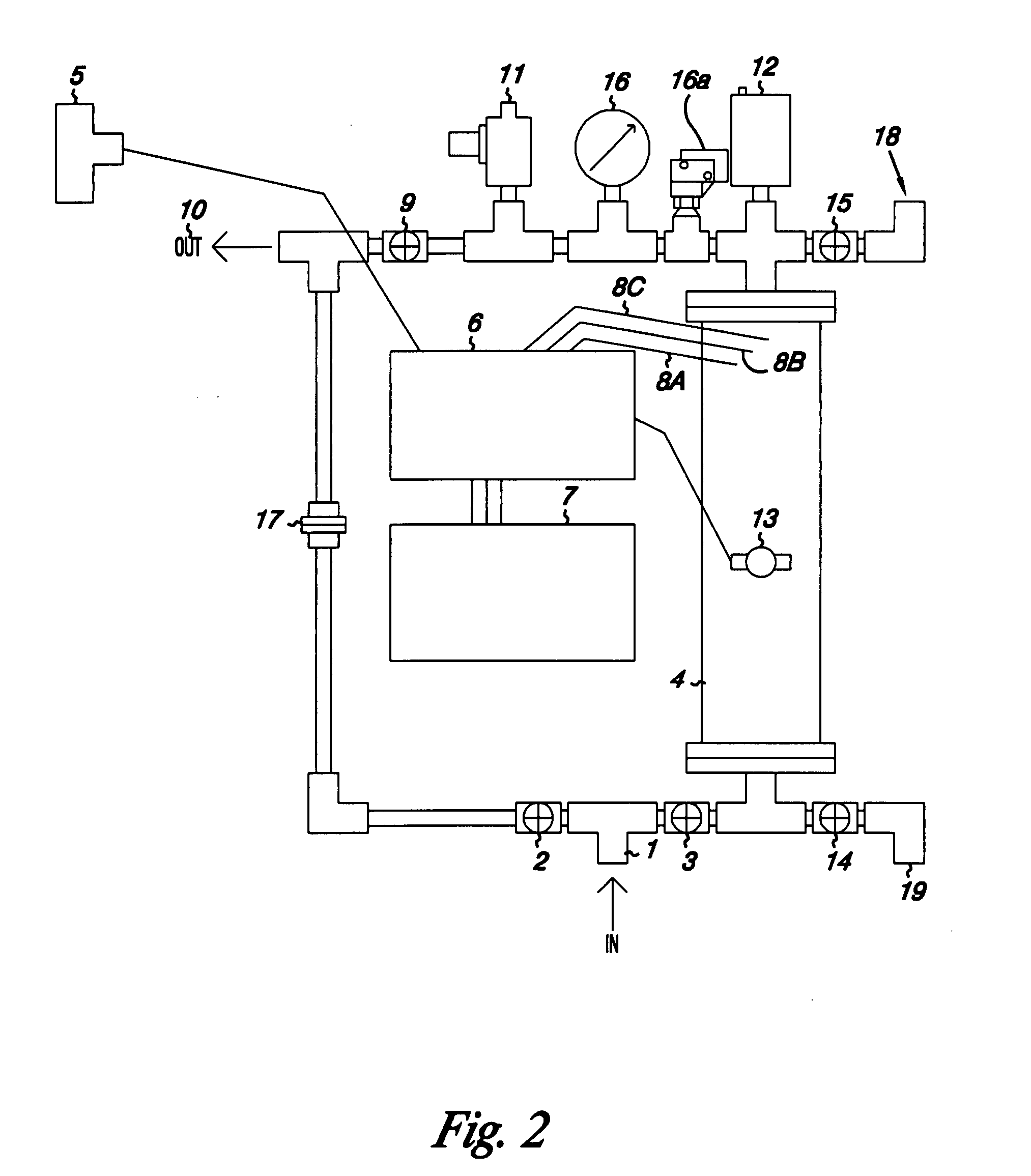
[0027]Turning to FIG. 2 the intake 1 is attached to the water supply to be treated. Valve 2 is shut; valve 3 is open to allow water into the electrolysis chamber 4. Valves 14 and 15 are closed. When the flow switch 5 connected to the controller 6 senses the water flow, the power supply 7 applies voltage to the plates 8a, 8b and 8c, causing oxygen to be evolved. The...

example 2

Description of Circuit Operation

[0033]This description is based on a example system with three emitters and the self cleaning polarity reversal on each initiation of water flow. Adjustments can be made for bigger or smaller systems. Circuit operation starts with applying line voltage, 120 V AC, to the power supply 26, which transforms the line voltage to 12 V DC. The controller circuit is in electrical communication with flow switch 23, temperature sensor 22 and push button switch 21 which activates the circuit, if the temperature sensor 22 indicates cool, thereby allowing 12 volts to be applied to the push button switch 21. When this push button switch is pushed, it energizes relay 24 K1A. The connections on this relay are such that it remains energized after the push button is released. The other contacts on this relay look at the flow switch to see if water is flowing. If so, the next relay 25 K1B is energized, applying 120 V AC to the second power supply 20 and relay 27 K2. K2 i...

example 3

Emitter Configurations

[0036]Depending on the volume of fluid to be oxygenated, the emitter of this invention may be shaped as a circle, rectangle, cone or other model. One or more may be set in a substrate that may be metal, glass, plastic or other material. The substrate is not critical as long as the current is isolated to the electrodes by the nonconductor spacer material of a thickness from 0.005 to 0.140 inches, preferably 0.030 to 0.075 inches, most preferably 0.065 inches. Within this distance, micro- and nanobubbles of oxygen are evolved. These bubbles are so small that they cannot escape and build up into what may be termed a colloidal suspension of oxygen in an aqueous medium. Oxygen concentrations of 260% of calculated saturation at a particular temperature and pressure have been achieved in a stationary container. The oxygen suspension in a flow-through unit can be so concentrated with oxygen that the water appears milky. In addition to the high oxygen content achieved, ...


PUM

PropertyMeasurementUnit
Fractionaaaaaaaaaa
Distanceaaaaaaaaaa
Distanceaaaaaaaaaa

Abstract

A system for the treatment of water to remove metals and undesirable substances from well and groundwater so as to render the water potable is disclosed. The system employs microbubbles of oxygen, which remain suspended in water at a concentration above 100% of the calculated saturated concentration at a particular temperature and pressure. These microbubbles oxidize undesirable substances in the water, which substances include iron manganese, arsenic, antimony, chrome, aluminum, reduced sulfur compounds, pesticide residues, drug metabolites and/or bacteria. Microbubbles are produced by electrolysis or by sparging through a microorifice. A control system for the electrolytic system is disclosed.

Description

RELATED APPLICATIONS[0001]This application claims priority of U.S. Provisional Application Ser. No. 60 / 813,267, filed Jun. 13, 2006.FIELD OF THE INVENTION[0002]The invention pertains to treatment of water to remove metals and undesirable substances from well and groundwater so as to render the water potable.BACKGROUND OF THE INVENTION[0003]Water for domestic, industrial and farm use frequently is contaminated with minerals, organic substances, and bacteria that render the water unpotable and even dangerous to health. Among these contaminants is ferrous iron, which forms a colloidal mass with water and fouls plumbing. Manganese and arsenic, both toxic metals, are frequently found in water. Another is hydrogen sulfide, which imparts a rotten egg smell to the water. Organic substances may include pesticide residues, drug metabolites and other contaminants that are released into the groundwater. Harmful bacteria such as Salmonella sp., E. coli, Shigella sp. and Clostridia sp. have been ...

Claims


Application Information

Patent Timeline
IPC IPC(8): C25C7/02
CPCC02F1/001C02F1/283C02F1/4672C02F2101/101C02F2101/103C02F2101/203C02F2201/4617C02F2101/22C02F2101/306C02F2201/46125C02F2201/4613C02F2201/46145C02F2101/206
Inventor HEGEL, RUDOLPH R.SORENSEN, ROBERT K.
Owner OXYGENATOR WATER TECH
Why Eureka
Try Eureka